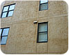
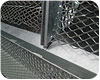
One piece control joints with cement stucco. Note: A double horizontal control joint at floor line to accommodate lumber shrinkage.
Portland cement plaster (aka stucco) has a wide range of qualities that make it a cladding suitable for virtually all regions, climates and building types. The only downside is the cracking issues that all cement products are susceptible. It is often the desire to minimize the cracking in the cement for an aesthetically pleasing and weather-resistant finish. It is also universally agreed that cracks in cement stucco are a form of stress relief. The most common practice employed to relieve or control the stress is with control and/or expansion joints. Both are trim accessories made from metal or plastic and specifically designed for cement stucco systems. Control joints are the most common trim accessory used to alleviate the stress.
Expansion joints are not control joints and the two should not be confused. Many consultants have made the mistake of trying to push the limits of a control joint’s capability to work like an expansion joint. An analogy could be comparing trucks. A three-quarterd ton pick-up truck loaded with two pallets of cement will fail. It is not the truck’s or manufacturer’s fault. There are larger, more robust trucks designed to handle the heavier loads.
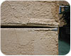
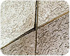
Horizontal control joint at floor line crushed (closed) from lumber shrinkage.
A control joint is a one-piece trim accessory used to relieve “minimal” amounts of stress, provide architectural breaks or aesthetic appeal. Cement shrinkage, thermal expansion and contraction, minor lumber shrinkage, and other minimal building movement are functions capable for the one-piece control joint to handle. Control joints have been used in cement plaster for many decades with great success, when their limitations are understood.
Control joints are made from steel, plastic or zinc and have varying degrees of flexibility. Generally, control joints are designed to accommodate movement of less than 1/4 inch and in only one direction. The most common usage of control joints are:
To divide up large panels
At the apex of doors and windows
Floor lines on low rise framed buildings
Aesthetic articulation
Dissimilar substrates or changes in framing
Thermal expansion and contraction
Cement volume loss during the cure time
As a screed
The control joint is very similar in function to the control or construction joint in flat concrete work. Prior to the invention of plaster trim accessories, plasterers would hold a rod (straight edge) and score a line into the soft brown coat of plaster. This would provide a natural breakpoint to produce a straight line crack rather than the random crack. Similar to the score lines concrete finishers use on concrete walkways. The plastering industry uses the one-piece control joint trim for a cleaner look, but the purpose is the same. No one would expect a score line (construction joint) in a concrete sidewalk to function as an expansion joint.
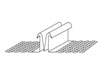
One-piece control joint (XJ-15 x-wing)
Recent testing that was conducted on one-piece control joints is very interesting but a moot point. The stresses where control joints are used in “real life” situations is not the same stress simulated in “pull-apart” testing. Pull-apart testing is taking the control joint and pulling the flanges in opposing directions to the point of failure. One-piece control joints are typically placed over a solid framing member or sheathing. For the pull-apart stress to occur in a significant force to pull open the control joint, the framing or sheathing would have to equally pull itself apart. While there is stress in opposing directions, it is very minor.
Contrary to popular belief, stress testing has been done on walls and in particular for openings such as windows to determine where the stress comes from and where it goes. The Armour Research Foundation conducted a series of experiments on stress, within plaster and how they interact with each other. The report was released in the ’50s and the data used in the 1960 “Manual of Lathing and Plastering.” On the basis of photolastic studies, the Armour Foundation concluded that the 90 degree corner of square openings, such as windows, was where stress tended to concentrate and then radiate outward and dissipate. The Bakelite test specimen was under the same racking loads condition found on typical exterior walls and clearly demonstrates the stresses walls face under racking loads. The testing also clearly proved the stress was unpredictable and with no repeatable pattern as it radiates outward.
This study led the plastering industry to start making recommendations of placing one-piece control joints at the corner of rectangular openings, as this was the focal point of stress concentration. This standard practice has been used for the last five decades.
There is the possibility of stress opposing directions on the control joint, shrinkage during the volume loss of moisture or thermal contraction. Both are very minor forms of stress and all one-piece control joints have proven capable and sufficient to handle these minor stresses.
Industry testing has also been done on control joints and their function with regard to cement shrinkage and thermal expansion and contraction. Vertical control joints do not noticeably open and close, even in significant temperature swings when temperatures would range from 50 degrees F to just over 100 degree F in short periods of time.
Horizontal control joints can often collapse (close) as green or wet wood plate lines shrink. Many believe that the use of more “green” lumber in recent years, framing practices and seismic requirements has led many designers to specify the more heavy duty two-piece expansion joint at floor lines.
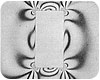
Photolastic stress testing by the Armour Research Foundation has been the basis for control joints in plaster for more than 50 years.
THE EXPANSION JOINT
An expansion joint is a two-piece telescoping trim accessory used to allow for greater anticipated building movement and often times in more than one direction. Seismic joints and at floor lines of multi-story buildings are common usages for the two-piece expansion joint. In some seismic regions these are often referred to as “story drift” joints. On large buildings, expansion joints may be advised for dissimilar substrates or changes in framing.The expansion joint is intended for some serious movement and requires more than a simple score line or break in the cement membrane. And like concrete work, there are a variety of styles and shapes for the expansion joint. The main feature is the allowance for greater movement than the small movement of the one-piece control joint.
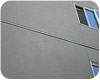
A one-piece control joint “honoring” a horizontal two-piece expansion joint.
The architect of record is the person to decide on the style of the joint and the layout pattern for the control/expansion joint. He/she should be most familiar with anticipated stresses the building is likely to incur during its service life and is in control of the aesthetics. The plastering contractor can provide some guidance to assist the architect. If the plastering contractor is certain the architect is making a mistake, he/she should notify the architect in writing with back-up documentation from a recognized authoritative source to clarify his/her position and then proceed only as directed by the architect.
Contractors: If there is confusion between the specifications and the drawings, ask what is intended by the designer. Do not assume, preach, delete or add anything without talking to the designer of record and getting anything that sounds wrong to you in writing as a directive.
Architects: Follow and reference ASTM standards, and if they do not meet what your owners desires are, call your local plaster association or bureau and seek assistance or clarification. Alterations to the code and ASTM standards are allowed, if either the designer of record and/or the building official approves the alteration. Most building officials are extremely reasonable and if public safety is accounted for; will allow design flexibility with authoritative back up.

A corner crack or “re-entrant” crack.
Here is where architects, contractors and defect experts really get confused. The model codes used around the United States historically had no requirement for control or expansion joints with stucco. These codes have now been blended into a single code known as the International code. The “I” code is reference-based and brings in many of the ASTM standards as part of the code. So many mistakenly believe that a designer must follow the ASTM with absolutely no exceptions and any installation contrary to the ASTM language is a violation of the code. This is not totally correct.
There is someone more important than ASTM and the I codes. This person has the ultimate authority to determine what is code approved or rejected. He/she can make, alter or modify any rule they see fit. This is the local building official, the building inspector’s boss, and he/she has the ultimate authority to accept, modify, alter or delete any code language as they determine relevant to their jurisdiction. However, even this important person also has his/her limitations, as the architect of record also has some serious clout on the project. While the architect cannot violate code minimums, such as reducing two hour rated walls to one hour rated walls, he/she can place design requirements more stringent than the code and override even the building official: the building inspector is required to follow the higher standard set by the architect. Unfortunately or fortunately, with regard to the code, the building owner, manufacturer, contractor and his subcontractors have little or no clout.
Building officials and architects make the rules and that is how it works. Since they have to know about every part of the building from the foundation to the electrical systems, they rarely have expertise on control or expansion joints for cement plaster systems. As such, they often rely on manufacturer’s data or recognized experts in the field of stucco, such as the Technical Services Information Bureau, The Northwest Wall and Ceiling Bureau, the Minnesota Lath and Plaster Bureau, Association of Wall and Ceiling Industries, or The Lathing and Plastering Institute of Northern California. These groups strive to serve the plaster industry as a whole, and the design plus code enforcement communities rely on what they say for code and design guidance.
The lath was cut behind the vertical control joint without adequate framing to support terminations of lath.
Be Square:Control joints should be used to create panels as square as possible. A long thin panel will tend to crack in segmented sections. L shaped panels tend to crack at the interior of the apex of the corner and radiate outward. This is often referred to as a re-entrant type crack. Generally, panels are recommended not to exceed a length to width ratio of 3:1; the closer to square, the better.
Size matters:Panels that do not exceed 144 square feet tend to resist cracking better than larger panels on framed walls. Since no one can guarantee panels kept to 144 square feet or smaller will not crack, some latitude should be afforded the designer to increase the panel size for aesthetic concerns. There is a limit, and if the goal is to minimize cracking, the maximum recommended size would be around 180 square feet. The distance between control joints should not exceed 18 to 20 feet.
Consider specifying two-piece expansion joints at floor lines to accommodate for greater movement from framing compression, seismic, wind, lumber shrinkage, etc. While one-piece control joints have worked for decades at these floor lines, today’s “fast growth” lumber has wider growth rings and tend to shrink more than lumber in past decades.
If the aesthetic design of the building does not lend itself to control joint articulation, architects have two options: accept that more cracking is likely or specify a basecoat and fiberglass mesh to be applied over the brown coat. Both do not conform to ASTM standards, but may be done per the Architect of Record desire and Building Official approval.

A vertical control joint where the lath was cut with insufficient framing for lath attachment.
ASTM C 1063 calls for the lath not to be continuous behind the control joint. While the recent independent testing conducted on one-piece control joints confirm that the joint is allowed to open wider when the lath is discontinuous; this is not how the control was designed or required to function as intended. However, this is not to prevent a designer or contractor that desires cutting the lath. A designer concerned with the issue of continuous or non-continuous lath behind the control joint should note other facts and consider a few related questions about control joints.
Until 2008, ASTM had no definition or differentiation between a control joint or expansion joint, all were control joints. The new ASTM definition is a good start, but is very vague and of little help to designers, contractors and code authorities.
How much movement are you demanding from the one-piece control joint? Possibly a two-piece expansion joint might be more appropriate if there is significant movement anticipated at that location. Why not specify the appropriate trim item, the two-piece expansion joint? Industry Plastering Bureaus recognize the difference from a control to an expansion joint and call for the lath to be discontinuous at expansion joints and a separation of framing.
One-piece control joints have been placed over continuous lath for decades on millions of square feet of plaster with no reported deleterious effects; this is not opinion, but fact. A one-piece control joint used where an expansion joint is better suited, will fail regardless if the lath is continuous or discontinuous.
If the lath is to be discontinuous behind the vertical one-piece control joint, one must make certain that there is appropriate framing to have both vertical lath terminations attached to framing. If the framing and sheathing is complete with inadequate support for the vertical lath terminations, the architect should be notified of the potential problem and asked how to proceed (see Rule 1). Architects can then use documents from the TSIB, NWCB or other recognized authority to verify that a one-piece control joint over continuous lath is recognized and an accepted and proven industry practice. (Again read Rule 1 and the section “The Code.”)
Floor line expansion joint with weep.
Cement stucco over masonry does not have the same rules or requirements as cement stucco over framed walls. The simple truth is, if the masonry wall cracks, the cement stucco will also crack, regardless of if and where you placed control joints in the stucco system. The primary use of control joints over masonry substrates is for aesthetics and a place for plasterers to start and stop work to avoid start and stop joints in large walls. Basic guidelines for control joints over masonry:
An expansion joint in the masonry must be honored in the stucco system.
Panels should be kept to approximately 200 to 220 square feet to minimize cold joints.
Lath (when used) may be continuous or cut at the control joint.

A reveal where the lath did not cover the solid nailing flange allowed the stucco to crack along the buried edge of the flange.
Expansion joints should govern over control joints.
It is recommended to have vertical control joints run continuous through horizontal control joints.
In areas exposed to frequent wind-driven rain, the intersections and terminations of control joints could be set in a bed or dab of sealant.
One-piece reveals are not as flexible as control joints, but do provide some stress relief and can be incorporated into the stucco system.
It is typically recommended to have the water resistant membrane continuous behind one-piece control joints and discontinuous at expansion joints with a weep provision. A WRB is typically not recommended for masonry substrates.
The lip of the trim accessory may or may not be covered in the finish coat of plaster; the method chosen should be uniform throughout the project.
It is not uncommon for a hairline separation between the trim accessory and the plaster to develop.
Lath should fully lap any solid attachment flange (more than 50 percent of the flange must be covered with a lath).
Placing a foam shape over a one-piece control joint is acceptable, with limitations.
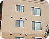
Building with through wall flashing expansion joints at the floor line and control joints.
One-piece control joints are similar to pick-up trucks and can handle light duty work/loads. Expansion joints are like flat bed trucks, they can handle quite a bit more than a pick-up, but even they have their limitations. No matter how many control/expansion joints are installed and where they are placed, the act of predicting exactly where, how severe and the direction stress will travel through the cement plaster is simply an educated guess. No designer, architect, contractor or consultant can guarantee a crack-free cement stucco membrane during the service life, and a hairline crack in cement stucco should not be considered a designer’s error or a construction defect. W&C


Report Abusive Comment