With changing energy code requirements, as represented in ASHRAE 90.1 or California’s Title 24, designers, engineers and contractors are facing practical challenges trying to meet these higher standards. One approach that is prescribed is the use of continuous insulation on the outside of building framing. While this approach does increase the insulating value of walls and reduces losses through thermal bridging, especially with steel framing, there is another option.
The incorporation of an air cavity or the concept of a double skin is not unique as air is known to be a good thermal insulation material and the concept has been utilized since the earliest of times. The Persian civilization utilized passive cooling systems as early as 3000 BC and became more sophisticated with the development of wind-catchers. In more recent times, double skin façade buildings were built in the U.S. and Europe in the 1970s during the first energy crisis to improve building energy performance. The double skin façade is a system consisting of two glass skins placed apart in such a way that air flows in the intermediate cavity. The ventilation of the cavity can be natural or fan supported. The origin and the destination of the air can differ depending on climatic conditions, building orientation and HVAC strategy.
Free Air
One of the key advantages of the air gap concept is that air is free. Further benefits are that the air cavity can be controlled-closed for heating cycles and open for cooling cycles. Air gaps are generally created by applying the cladding over spacers or furring strips. Various designs and concepts have evolved or been developed over the last few years. One example, a vented roof and wall system was developed and patented in 2009 by Cool Building Systems in San Antonio. Its system basically focused on roofs and walls of metal buildings but utilizes and controls the air cavity concept.Other companies are also developing new solutions utilizing air cavities to meet the changing energy targets. Structa Wire Corp. has recently developed a new stucco lath that is a one step, self-forming cavity lath for creating air gaps with stucco plaster. The lath is a 1-inch-by-1½-inch welded-wire lath with integrated furring spacers that automatically create a 3/8-inch cavity. A barrier kraft paper is placed within the lath at the 3/8 inch point to prevent stucco plaster from entering the cavity. A reflective foil is adhered on the cavity side of the barrier. Prototypes of this new lath have been created and photographs of front and back of this new lath are shown in the photos on the next page.

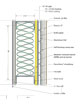
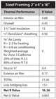
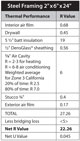
The wire crimps or spacers dramatically reduce the thermal bridging losses, which are especially critical with steel framing. Furthermore, with the combination of the air gap and the reflective insulation, it is expected that R will be improved by approximately 2 to 3 for heating or up to 6 to 8 for cooling. Depending on geographical location, the weighted average could be an R of 6, which would be typical for an example of Zone 3 in California. A cross section of such a proposed wall system with steel framing is shown in the figures above and on page 27.
The one inch of EPS would not be required for 2012 standards but would be an option for 2015 expected increased standards. Of course another option to achieve the higher standards would be to utilize 2x6 framing with R 19 batts in the wall cavity. Economic analysis would be required to determine which option would be most cost effective at that time.
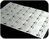
Backface of Self-Forming Cavity Lath with Refl ective Foil Insulation and Wire crimps for forming the thermal cavity.
Control the Air Flow
One of the key advantages of the air cavity is the ability to control the movement of air within. One version of the system would have the bottom of the air space open with a continuous opening, but with an insect screen to keep insects out. However, at the top, the cavity could also have a continuous opening, or preferably would have a series of motorized dampers that could open and close. These dampers then could be tied into the HVAC system in such a way that they would be closed during the heating cycles and open during the cooling cycle. In many locations in the U.S., the energy utilized for air conditioning greatly exceeds that for heating. Therefore, it is anticipated that the air cavity system would be even more advantageous in high air conditioning regions. A vast number of control options exist in how to control the dampers and could be programmed to anticipate rising temperatures and could differentiate between various elevations of the structure.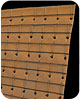
Front side of Self-forming Cavity Lath with kraft backing and furred lathing.
This concept and design has been submitted to various engineering groups, trade associations and contractors for peer review and feedback. The response has been unanimous in commending the concept as a brilliant approach to resolving a number of challenges.
“KHS&S is mainly involved in steel framing construction and thermal bridging losses are a significant loss estimated at 40 percent,” says Jim Stafford of KHS&S West. “We understand that experiments have been conducted utilizing various thermal spacers attached or fabricated on the face of steel studs before the DensGlass is installed. This process is difficult and benefits are limited. We have examined the Structa Wire concept and are very excited about the simplicity and effectiveness of the system and feel that it will address the changing energy requirements in an efficient and practical method. This air gap system will at the same time provide an effective drainage and drying cavity and this is huge.”
Structa Wire is presently performing hot box testing on assemblies with 2x4 and 2x6 wall assemblies with wood and steel framing to verify thermal performance. The company expects to have the manufacturing equipment in place by the end of 2011 for availability in 2012, in time to meet the changing code requirements.
In summary, air cavities are a time proven approach to improving the energy efficiency of buildings and can be further utilized to effectively and efficiently meet the requirements of new energy codes and construction going into the 21st century. An update on the research will be issued in due course.


Report Abusive Comment