At some point on a project, generally after the mechanical trades begin their installations, we are advised by the code official that we have framing deficiencies that will most likely result in a “failed report” unless corrective action is taken. All too often these deficiencies are the result of mechanical trades cutting, notching or boring holes into our framing members. It may be difficult, but not impossible to get a 3½-inch pipe through a 35⁄8-inch stud, however all you may be left with are the flanges on either side, holding the stud together.
We see this type of situation all too often and once we report the damage to the general, we are asked something to the effect of, “Just how much material can be removed from studs without compromising their integrity?” The question is just a little puzzling, because as a light gauge metal framing contractor, we don’t notch or bore holes into our studs. We install them as they come from the factory, with the factory punch-outs and any further modifications to the members are generally by other trades. These factory punch-outs are intended to accommodate bridging members, as well as electrical, fuel gas, plumbing elements, etc., and when provided by the factory, are intended to prevent random notching or boring that could otherwise compromise the integrity of the stud.
The Steel Stud Manufacturers Association ICBO ER-4943P is very specific as to the location of these punch-outs. General Note #4 states: “When provided, factory punch-outs will be located along the centerline of the webs of the members and will have a minimum center-to-center spacing of 24 inches. Punch-outs will have a maximum width equals half the member depth (d/2) or 2½ inches, whichever is less, and a maximum length equals 4½ inches. The minimum distance between the end of the member and the near edge of the web punch-out equals 10 inches.” Engineering by the SSMA has determined that punch-outs meeting these criteria will not compromise the integrity of the stud.
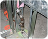
Torch cutting for plumbing installations.
CLEAR AND VAGUE
Although the IBC is very specific about notching or boring holes in wood framing members, when it comes to cold-formed steel, the IBC is a little vague. The code references the General Provisions of the American Iron and Steel Institute, the AISI-NASPEC and ASTM Standards.ASTM C1007 Section 8.9.4 reads, “Cutting of flanges in stud and joist framing members shall not be permitted.” Section 8.9.5 states, “Cutting of additional holes other than those provided by the manufacturer in framing members shall not be permitted.”
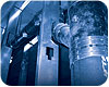
Boring holes for plumbing installations.

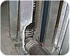
Cutting and notching for electrical installations.
This is not the responsibility of the framing contractor. If notching or boring appears to be necessary to accommodate MEP elements, it is the responsibility of the affected MEP trade to request direction from the Design Professional. Furthermore, it is the responsibility of the Design Professional to ensure the accuracy of the project documents and to make certain that the information presented in the documents will accommodate, without compromise, all building elements specified for the project. W&C


Report Abusive Comment