High-Performance Building Envelope: Maximize Energy Efficiency
Interaction between HVAC and building enclosure design is the secret to maximizing energy efficiency.
Continuous air barrier systems will be mandated for new commercial construction under Addendum z to the 2007 version of ANSI/ASHRAE/IESNA Standard 90.1, Energy Standard for Buildings Except Low-Rise Residential Buildings, which provides minimum requirements for the energy-efficient design of buildings. The standard contains changes made through 47 addenda to the 2004 standard, including Addendum z, which establishes performance requirements for air leakage of the opaque building envelope.
Addendum z has been in development and approvals for four years and was voted upon at the ASHRAE winter meeting by three committees: the Standards Committee, the Technical Council, and the ASHRAE Board of Directors, which passed it unanimously. Because Standard 90.1 is under continuous maintenance, Addendum z will be published and become effective in coming weeks, and will be included in the body of the 90.1 Standard in 2010.
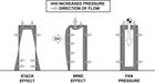
There are three major sources of pressure that cause air to leak: wind pressure, stack pressure and HVAC fan pressure. Of the three, wind is usually the greatest. Over the course of a year, this is about 10-15 mph (0.2-0.3psf or 10-14Pa) in most locations in North America. With it, air enters the envelope on the windward side and exits on the other three sides and at the top, through the roof.
Stack pressure, also referred to as stack effect or chimney effect, is caused by buoyancy. The weight of the column of conditioned air inside the building compared with that outside creates a pressure difference across the building envelope. Warm, conditioned air escapes through holes at the top of the building and at the roof. The resulting lower pressure at the bottom of the building draws in air from the surrounding environment.
The third pressure comes from the mechanical system itself. Mechanical engineers and on-site managers often choose to bring in makeup air to increase pressure and overcome the infiltration at the base of the building. Unfortunately, this increases pressure at the top, causing more exfiltration problems in that area.
A groundbreaking 2005 report from the National Institute of Standards and Technology (NIST), Investigation of the Impact of Commercial Building Envelope Airtightness on HVAC Energy Use, confirmed that continuous air barrier systems could reduce air leakage by up to 83 percent and energy consumption for heating and cooling by up to 40 percent.
The study evaluated the energy savings of an effective air barrier requirement for non-residential buildings in five cities representing different climate zones. The methodology included blended national average heating and cooling energy prices and cost effectiveness calculations matching the scalar ratio employed by ASHRAE SSPC 90.1. Energy simulations were performed using TRNSYS (Klein 2000). Simulations of annual energy use were run using TMY2 files (Marion and Urban 1995).

The office building model in the study was a two story office building with a total floor area of 2250 m (24,200 ft) and a window-to-wall ratio of 0.2 with a floor-to-floor height of 3.66 m (12 ft), broken up between a 2.74 m (9 ft) occupied floor and a 0.92 m (3 ft) plenum per floor. The building also included a single elevator shaft.
The internal gains for the occupied spaces were divided into three parts: lighting, receptacle loads and occupants. The thermostats operated on a setpoint with setback/setup basis. The heating setpoint was 21.1 C (70 F) with a setback temperature of 12.8 C (55 F) and the cooling setpoint was 23.9 C (75 F) with a setup temperature of 32.2 C (90 F). The HVAC system included water-source heat pumps (WSHPs) with a cooling tower and a boiler serving the common loop. Each zone had its own WSHP rejecting/extracting heat from the common loop. The outdoor air for each zone was supplied to each individual heat pump, and the heat pump blower was on at all times when the zone was occupied. When the location of the building required an economizer, the outdoor air controls were applied to the individual heat pump’s airflow. With this approach, different heat pumps could have a different percentage of outdoor air at the same time depending on the loads. Three of the modeled locations included economizers and two did not. Return airflow was specified to equal 95 percent of supply airflow.
The results showed that reducing the air leakage rate to the target level by including a continuous air barrier system resulted in an average reduction in infiltration of 83 percent. The economic impact is shown in Table 1, accompanying this article.
Many states reference ASHRAE 90.1 in lieu of a unique State Commercial Energy Code, and the performance criteria outlined in Addendum z are similar to the air barrier requirements in previously published Commercial Energy Codes of Massachusetts, Wisconsin and Michigan, as well as the Canadian National Building Code, which has included air barrier systems for several decades.
It is expected that the inclusion of air barrier requirements in Standard 90.1 will provide momentum to similar requirements developed by the American Institute of Architects (AIA) and proposed to the International Energy Conservation Code (IECC) committee for adoption in the next round of Code changes.
The Air Barrier Association of America (ABAA) has published Master Specifications for several different air barrier materials and systems that meet the performance requirements of state and model Energy Codes on its Web site: www.airbarrier.org. The ABAA also provides training programs for architects, specifiers and engineers, as well as a certified installer program with third-party quality control inspections to ensure correct installation of the systems.
Here is a list of additional resources on the air barrier and its impact on HVAC performance:
• The National Institute of Standards and Technology (NIST): www.nist.gov
• The Air Barrier Association of America: www.airbarrier.org
• Oak Ridge National Laboratory: www.ornl.gov
• The United States Department of Energy: www.energy.gov
• American Society of Heating, Refrigerating and Air-Conditioning Engineers (ASHRAE): www.ashrae.org
• The National Institute of Building Sciences (NIBS), Whole Building Design Guide: www.wbdg.org
• Canada Mortgage and Housing Corporation (CHMC): www.cmhc-schl.gc.ca
• National Research Council of Canada: www.nrc-cnrc.gc.ca
• BASF Polyurethane Foam Enterprises LLC: www.basf-pfe.com
Continuous air barrier systems will be mandated for new commercial construction under Addendum z to the 2007 version of ANSI/ASHRAE/IESNA Standard 90.1, Energy Standard for Buildings Except Low-Rise Residential Buildings, which provides minimum requirements for the energy-efficient design of buildings. The standard contains changes made through 47 addenda to the 2004 standard, including Addendum z, which establishes performance requirements for air leakage of the opaque building envelope.
Addendum z has been in development and approvals for four years and was voted upon at the ASHRAE winter meeting by three committees: the Standards Committee, the Technical Council, and the ASHRAE Board of Directors, which passed it unanimously. Because Standard 90.1 is under continuous maintenance, Addendum z will be published and become effective in coming weeks, and will be included in the body of the 90.1 Standard in 2010.
MANDATING HIGH PERFORMANCE
Why would HVAC engineers decide to mandate high-performance building enclosures? An effective, continuous air barrier system controls air movement into and out of the building, allowing the HVAC system to do its job uncompromised by the loss of conditioned air due to “uncontrolled” air leakage. The United States Department of Energy estimates uncontrolled air leakage can account for 30 percent or more of a building’s heating and cooling costs, and contribute to problems with moisture. Air leakage occurs through cracks, gaps, holes, pores in materials and other openings in the building envelope. When air leaks, it takes with it heat, water vapor, smoke, pollutants, dust, odors, allergens and anything else it can find and carry.There are three major sources of pressure that cause air to leak: wind pressure, stack pressure and HVAC fan pressure. Of the three, wind is usually the greatest. Over the course of a year, this is about 10-15 mph (0.2-0.3psf or 10-14Pa) in most locations in North America. With it, air enters the envelope on the windward side and exits on the other three sides and at the top, through the roof.
Stack pressure, also referred to as stack effect or chimney effect, is caused by buoyancy. The weight of the column of conditioned air inside the building compared with that outside creates a pressure difference across the building envelope. Warm, conditioned air escapes through holes at the top of the building and at the roof. The resulting lower pressure at the bottom of the building draws in air from the surrounding environment.
The third pressure comes from the mechanical system itself. Mechanical engineers and on-site managers often choose to bring in makeup air to increase pressure and overcome the infiltration at the base of the building. Unfortunately, this increases pressure at the top, causing more exfiltration problems in that area.
A groundbreaking 2005 report from the National Institute of Standards and Technology (NIST), Investigation of the Impact of Commercial Building Envelope Airtightness on HVAC Energy Use, confirmed that continuous air barrier systems could reduce air leakage by up to 83 percent and energy consumption for heating and cooling by up to 40 percent.
The study evaluated the energy savings of an effective air barrier requirement for non-residential buildings in five cities representing different climate zones. The methodology included blended national average heating and cooling energy prices and cost effectiveness calculations matching the scalar ratio employed by ASHRAE SSPC 90.1. Energy simulations were performed using TRNSYS (Klein 2000). Simulations of annual energy use were run using TMY2 files (Marion and Urban 1995).
Table 1.
AIRTIGHT VS LEAKING BUILDINGS
The research team selected whole building airtightness levels that were judged to be readily achievable and used these in the energy modeling exercise as the whole building target. The baseline buildings used in the comparison were modeled with leakage levels based on a database of commercial building leakage measurements.The office building model in the study was a two story office building with a total floor area of 2250 m (24,200 ft) and a window-to-wall ratio of 0.2 with a floor-to-floor height of 3.66 m (12 ft), broken up between a 2.74 m (9 ft) occupied floor and a 0.92 m (3 ft) plenum per floor. The building also included a single elevator shaft.
The internal gains for the occupied spaces were divided into three parts: lighting, receptacle loads and occupants. The thermostats operated on a setpoint with setback/setup basis. The heating setpoint was 21.1 C (70 F) with a setback temperature of 12.8 C (55 F) and the cooling setpoint was 23.9 C (75 F) with a setup temperature of 32.2 C (90 F). The HVAC system included water-source heat pumps (WSHPs) with a cooling tower and a boiler serving the common loop. Each zone had its own WSHP rejecting/extracting heat from the common loop. The outdoor air for each zone was supplied to each individual heat pump, and the heat pump blower was on at all times when the zone was occupied. When the location of the building required an economizer, the outdoor air controls were applied to the individual heat pump’s airflow. With this approach, different heat pumps could have a different percentage of outdoor air at the same time depending on the loads. Three of the modeled locations included economizers and two did not. Return airflow was specified to equal 95 percent of supply airflow.
The results showed that reducing the air leakage rate to the target level by including a continuous air barrier system resulted in an average reduction in infiltration of 83 percent. The economic impact is shown in Table 1, accompanying this article.
AIR BARRIER CHRACTERISTICS
Air barrier systems must be constructed of materials with an air permeance rating of less than 0.004 cfm/ft (0.2 L/sm at 75 Pa) when tested at their intended-use thickness in accordance with ASTM E 2178. They must be continuous throughout the building envelope with interconnected, flexible joints. The air barrier must be able to withstand positive and negative air pressures without displacement and must be durable enough to last the life of the building. All penetrations in the air barrier must be sealed.Many states reference ASHRAE 90.1 in lieu of a unique State Commercial Energy Code, and the performance criteria outlined in Addendum z are similar to the air barrier requirements in previously published Commercial Energy Codes of Massachusetts, Wisconsin and Michigan, as well as the Canadian National Building Code, which has included air barrier systems for several decades.
It is expected that the inclusion of air barrier requirements in Standard 90.1 will provide momentum to similar requirements developed by the American Institute of Architects (AIA) and proposed to the International Energy Conservation Code (IECC) committee for adoption in the next round of Code changes.
The Air Barrier Association of America (ABAA) has published Master Specifications for several different air barrier materials and systems that meet the performance requirements of state and model Energy Codes on its Web site: www.airbarrier.org. The ABAA also provides training programs for architects, specifiers and engineers, as well as a certified installer program with third-party quality control inspections to ensure correct installation of the systems.
Here is a list of additional resources on the air barrier and its impact on HVAC performance:
• The National Institute of Standards and Technology (NIST): www.nist.gov
• The Air Barrier Association of America: www.airbarrier.org
• Oak Ridge National Laboratory: www.ornl.gov
• The United States Department of Energy: www.energy.gov
• American Society of Heating, Refrigerating and Air-Conditioning Engineers (ASHRAE): www.ashrae.org
• The National Institute of Building Sciences (NIBS), Whole Building Design Guide: www.wbdg.org
• Canada Mortgage and Housing Corporation (CHMC): www.cmhc-schl.gc.ca
• National Research Council of Canada: www.nrc-cnrc.gc.ca
• BASF Polyurethane Foam Enterprises LLC: www.basf-pfe.com
Looking for a reprint of this article?
From high-res PDFs to custom plaques, order your copy today!


