The Finish Line: Keep it Dry Part 2
Drawing 1
In the May column “Keep it Dry,” I talked about issues to be dealt with when using EIFS that incorporate a water resistive barrier. WRBs are most often used in the increasingly common EIFS with drainage. Most of the discussion in that article was about various design aspects. This month’s column will show examples, via drawings, of various common WRB conditions.
Types of Water Resistant Barriers
Some WRBs are applied with a trowel like the EIFS itself. Some can be spray-applied like paint. These two types stay in place by continuous bonding to the substrate. Other WRBs are sheet materials that are mechanically fastened, usually with staples (like building paper). This type can be installed by non-EIFS contractors but usually it’s better to have the EIFS contractor do the entire EIFS, including the WRB.With sheet-type WRBs, the sheets must be overlapped shingle style. This presents the opportunity for slipping flashings behind the WRB or sticking sealant tapes to the surface-a handy feature-but also requires attaching the EIFS with mechanical fasteners.
Drawing 2
WRB Detail Drawings
As with traditional EIFS, there are many variations of how EIFS with drainage can be detailed and installed. Each EIFS producer has their own way, but there are many similarities from one product brand to another. The details (drawings) in this piece were provided by BASF Wall Systems and reflect the product names. The numbers on the drawings are used to guide you to the various design aspects of the detail that I will discuss (such as “1”, “2”, etc.)Bottom-of-Wall
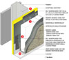
Drawing 1 is of a detail at the bottom of an EIFS wall. In Area 1, note how the joint between the ends of the sheathing pieces is taped together and a liquid-applied WRB is applied over the sheathing and tape. This helps maintain the continuity of the WRB should the supporting framing and sheathing move (which might crack the WRB). In Area 2 are the thick vertical stripes of adhesive used to attach the insulation to the WRB. This creates a drainage cavity. In Area 3, the layer of reinforcing tape is embedded in WRB materials and is lapped over the flashing below. This maintains the continuity of the WRB. In Area 4, note that the bottom of the wall must be left open so the water can leave the cavity. This can be done with a flashing or a simple slot. If the slot is large and wide open, crawling bugs such as termites near the ground can get in behind the EIFS insulation. The same is true at window heads with flying insects.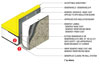
Drawing 3
Window Head
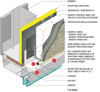
The window head in Drawing 2 is for the common condition where the outside face of the window frame is in line with the outside of the EIFS. In this case (note in Area 1) that the bottom edge of the EIFS is sealed shut to the flashing with caulking. But doing so continuously would seal whatever water might be flowing down in the drainage cavity, trapping it at the window head. In this design, shown in Area 2, weep tubes (plastic straws) are embedded in the sealant to allow the water to get out. This can also be accomplished by leaving small gaps in the sealant bead. In Area 3, note that the underside of the flashing has caulking between it and the window frame.Soffit
The detail in Drawing 3 shows a transition between a vertical EIFS wall-perhaps a fascia-and an EIFS soffit. This is a “trimless” detail (no flashing). The drainage for the fascia is via an open slot at Area 1. Note that in Area 2 that the EIFS is not an EIFS with drainage but rather a traditional barrier EIFS.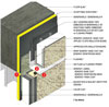
Drawing 4
Floor Line
Drawing 4 is an important one. It applies to floor line joints as well as to expansion joints. It’s an especially important detail in wood frame residential construction where EIFS with drainage is often required by code. It is similar to the bottom-of-wall detail in Drawing 1, except that it also has EIFS below it. The key is Area 1, where a flexible tape is used to allow movement of the floor and framing without breaking the WRB. The same would apply to expansion joints (vertical and horizontal).In Area 2, the WRB is terminated with a flashing so the water can drain out. In Area 3, the lower EIFS is caulked shut so that water cannot get blown up under the flashing. Otherwise, a flashing with a long vertical leg that is potentially ugly would be needed.
The Finish Line
The use of WRBs adds to the cost of an EIFS. Sometimes they must be used to meet building codes but sometimes they are specified by owners and designers to improve the performance of the wall. In any event, the key to the successful use of WRBs is in the details of how they-and related materials adjacent to them-are integrated. The drawings shown give you some idea of how these details are done. EIFS producers all have their own way of doing WRBs and the details and materials they want used in their systems should be followed. Additional examples of WRB details are readily available online on EIFS producers’ websites.Looking for a reprint of this article?
From high-res PDFs to custom plaques, order your copy today!


