Flashing and Integration
(or Lack Thereof) of Windows with Weather-Resistive Barriers
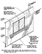
Figure 1
Lack of integration between windows and the building weather-resistive barrier is a systemic problem in many buildings that often leads to leakage within a wall system. Consequences of improper integration typically include leakage, damage to interior finishes and deterioration of wall components, such as sheathing and framing.
Our investigation of numerous building envelopes across the country reveals a high occurrence of wall failures stemming from deficiencies in window flashing and integration between windows (both flanged and non-flanged) and the weather-resistive wall barrier. These failures can be avoided through the execution of a properly designed, step-by-step process of window and flashing installation. The proof testing of full-scale mock-ups and follow-up testing during construction have shown these techniques to be successful.
This paper presents our investigative findings regarding window/wall integration failures, as well as our recommendations, and guidelines for flashing and integrating both flanged and non-flanged windows with weather-resistive barriers. We also include a review of current industry standards regarding window installation and compare our recommendations to these standards.
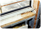
Figure 2
Introduction
Current industry standards and trade publications provide recommendations and guidelines for the installation of windows (both flanged and non-flanged) and perimeter flashings. We have researched and compared the following documents as they pertain to window and flashing installation, and the integration of these materials with the weather-resistive barrier:- Major Building Codes: 1997 Uniform Building Code (Volume 1), 1999 Standard Building Code, 1999 Building Officials & Code Administrators National Building Code, 2001 California Building Code, and the 2003 International Building Code
- The Plaster and Drywall Systems Manual, Third Edition, by Gorman, Jaffe, Pruter, and Rose, (issued in 1988)
- Nail-On Windows, Installation & Flashing Procedures for Windows & Sliding Glass Doors, DTA Inc. (1995)
- California Association of Window Manufacturers 400-95, Standard Practice for Installation of Windows with Integral Mounting Flange in Wood Frame Construction (issued in 1995)
- ASTM E 2112 - 01, "Standard Practice for Installation of Exterior Windows, Doors, and Skylights (issued in 2001)"
- AAMA 2400 - 02, "Standard Practice for Installation of Windows with a Mounting Flange in Stud Frame Construction (based on CAWM 400-95, issued first in 1995)"
- Canadian Standards Association, A 440.4 - 98, "Window and Door Installation"
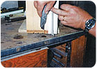
Figure 3
None of the documents requires a sill pan flashing at flanged windows; apparently the industry assumes that sill corners of these windows are permanently watertight inboard of the nailing flange. But this assumption is flawed since the sill corners of many windows leak. Rigid head flashings over flanged windows are optional in industry recommendations, however many windows cannot reliably collect and control water along the head. The lack of a rigid head flashing can lead to leakage, particularly in the case of ganged windows.
The industry needs to recognize and rectify these shortcomings or the present methods of material installation will continue to lead to building leakage and resultant deterioration of wall components as illustrated in latter sections of this paper.
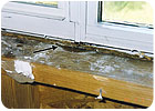
Figure 4
Overview of Industry Literature
The following is a summary of the recommendations and associated shortcomings contained in the documents that we reviewed.Building Codes
In general, building codes require the use of a weather-resistive barrier behind exterior claddings to protect underlying materials from weather. The codes also require that flashings be installed at fenestrations to prevent water from entering the building and concealed wall cavity.
The codes, by nature, are very broad and general in their requirements, and do not prescribe means and method for the installation of windows, the WRB and flashing.
Industry Publications
The beginnings of illustrated, step-by-step procedures for installing windows, perimeter membrane flashing and the WRB can be found in industry publications, such as the Plaster and Drywall Systems Manual and Nail-On Windows by DTA Inc. Both of these publications address flanged windows only.
The Plaster and Drywall Systems Manual includes a one-page procedure of the material installation sequence with relatively simple, two-dimensional illustrations. Nail-On Windows provides more detailed isometric drawings and associated notes (Figure 1).
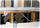
Figure 5
At head corners neither the membrane nor rigid head flashings discussed in these publications extends over the WRB. Water deposited to the head flashings can therefore flow off of the ends of the flashing directly behind the WRB.
National Standards
National Standards include step-by-step installation procedures for both flanged and non-flanged windows. For flanged windows, the standards present installation methods and isometric drawings similar to those found in Nail-On Windows. Consequently, the methods presented in the standards exhibit the same shortcomings discussed above.
Investigative Findings
The methods and recommendations contained in current industry literature and associated shortcomings (previously discussed) can lead to wall envelope failures. A case study of field observations and findings from numerous investigations of building envelope failures across the country, particularly in the South and Southwest, illustrates this point and is outlined below. Each included building leakage and resultant damage to wall components as a result of inadequate window perimeter flashing and poor integration between windows (both flanged and non-flanged), and the surrounding WRB and flashing.
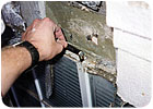
Figure 6
One of the most frequent contributors to leakage at the window-to-wall interface is the lack of a sill flashing pan.
The buildings we investigated incorporated residential grade aluminum-framed, clad wood or vinyl flanged windows. Windows were often installed in series to create ganged units in which the jamb extrusion of one window was dry-set into that of the adjacent window. Asphalt-saturated felt was generally the weather resistive barrier, with self-adhered (peel-and-stick) rubberized-asphalt flashing at window perimeters. Waterproofing materials terminated at the window nailing flange and did not turn into the rough opening (Figure 2). Isolation tests (i.e, water ponded within the window sill) resulted in window frame corner leakage at aluminum framed, clad wood and vinyl windows (Figures 2 and 3).
Leakage to the building interior also occurred through metal-to-metal joints at coped intersections in the framing (Figure 4). At ganged windows, water collected in the vertical race between ganged mullions and flowed directly to the unprotected window stool (Figure 5). The lack of a sill flashing pan allowed water from all of these leakage paths to enter the building, resulting in deterioration of wall components. Although a sill flashing pan (with an interior upturned leg and end dams) would have controlled this leakage, its absence at flanged windows is consistent with current industry literature.
Although the industry recognizes leakage at sill corners of non-flanged windows (both ASTM E 2112 and the Canadian Standards Association A 440.4 require sill flashing pans at non-flanged windows), none of the standards we reviewed requires flashing pans at flanged windows. This logic is inconsistent and flawed since frame corner construction is independent of the presence or lack of a nailing flange. The inclusion of a perimeter nailing flange has absolutely no influence or bearing on the watertightness of the window frame corner but yet the industry unrealistically assumes that flanged window units are watertight inboard of the nailing flange and will remain watertight throughout their service life.
Frame corners are sometimes constructed with thin and discontinuous applications of sealant and the mechanical joinery of residential frame corners is often relatively weak. During window assembly, water-tightness of the sill corners is addressed through the installation of liquid-applied sealant at the interface of the sill and jamb for both wood- and aluminum-framed windows, and by fusing or welding the sill corners of vinyl windows. These sill corners tend to leak for the following reasons:
- Discontinuous application of sealant in factory
- Loss of sealant adhesion due to water attack of bond line
- Loss of sealant adhesion due to differential movement of sill and jamb due to thermal changes
- Loss of sealant adhesion or cracked welds due to distortion of frame during handling, transportation and installation
- Insufficient factory welds
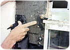
Figure 7
For many windows, particularly residential grade, leakage inboard of window nailing flanges is a common occurrence and installation methods must anticipate and accommodate this leakage. At both flanged and non-flanged windows, waterproofing materials must extend to the interior to create watertight sill flashing pans that capture and drain any leakage from window frame joints or ganged mullions. Sill pans need to have an upturned interior leg, down-turned leg at the exterior and end dams that do not rely on sealant for waterproofing integrity. As a minimum, sill nailing flanges should not be sealed but should contain intermittent weeps to allow any water within the sill flashing pan to drain. Fasteners should never penetrate the horizontal portion of the sill flashing.
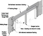
Figure 8
Current industry literature does not require the installation of a rigid head flashing at flanged windows but does include rigid head flashing at non-flanged windows. The nailing flange at the window head is not a substitute for a rigid head flashing, as industry literature infers, since many flanged windows are not designed to collect and control water along the head.
A rigid head flashing (preferably a durable, solderable metal, such as stainless steel, copper, or lead-coated copper), is essential at ganged window units (both flanged and non-flanged) to prevent water on the WRB from flowing directly into the open race formed at ganged mullions (Figure 6).
Concurrent installation of a metal head flashing with the WRB leads to a more continuous, watertight installation. This method avoids cutting diagonals in the WRB at window head corners to install the head flashing as outlined in many current industry standards and therefore eliminates the risk of these cuts going unsealed or being improperly sealed after the head flashing is in place.
To help ensure that water on the head flashing cannot drain behind the WRB (Figure 7), the WRB next to the window jamb should extend above the window head to a location above the top of the metal flashing flange (Figure 8). It is also essential that the continuous, watertight metal flashing flanges extend out over the WRB at the head corners.
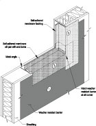
Figure 9
Over the years we have developed a method of window and flashing installation that can be applied to both flanged and non-flanged windows (with slight modification to account for the flanges). Our method, discussed below, differs slightly from those outlined in current standards, since flashings are installed concurrently with the WRB and we include sill flashing pans at flanged windows.
Unless noted otherwise, procedures discussed below pertain to both flanged and non-flanged windows.
Sill and Jamb Flashing
At non-flanged windows, a continuous metal angle (typically aluminum) is first anchored to the surrounding framing at the entire perimeter of the rough opening (Figure 9). The angle provides perimeter attachment for the window and also serves as a backing for a self-adhered membrane flashing sill pan and similar jamb flashing. The use of the perimeter attachment angle eliminates fastener penetrations in the horizontal surface of the sill flashing pan, which turns into the opening at the sill and jambs.
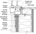
Figure 10
The WRB is installed to the rough opening at the sill and jambs. The WRB is notched at the sill corners as shown in Figure 9 to lessen the risk of a waterproofing "pinhole" in this area. Rubberized-asphalt self-adhered membrane forms the sill pan and turns up at the interior onto the metal angle at non-flanged windows (Figure 9) or similar backing at flanged windows (Figure 10). At sill corners, the membrane flashing turns up onto jamb framing to form end dams (Figure 9). Along the jambs of non-flanged windows, the flashing membrane extends from the WRB into the rough opening and terminates at the tip of the metal perimeter angle, shingling into the flashing pan at the sill. At flanged windows, jamb flashing extends from the nailing flanges to the adjacent WRB.
The WRB installed along the jambs must extend beyond the head of the rough opening. This enables the integral flanges of the metal head flashing to extend out over the WRB at head corners, which prevents water on the head flashing from flowing behind the WRB to unprotected wall components.
Window Installation
Immediately prior to window installation, non-flanged windows are set in a continuous sealant against the perimeter flashing and attachment angles. Similarly, jamb and head nailing flanges are set in a continuous sealant against the WRB and sheathing, respectively. Self-adhered membrane flashing is then installed between jamb nailing flanges and adjacent WRB. The sill nailing flange must not be sealed and should contain intermittent weeps to allow any water within the sill flashing pan to drain while still reducing air infiltration.
Head Flashing
A metal head flashing with integral flashing flanges caps the window and turns down the jambs (Figure 8). At head corners, the flashing flanges must extend over the WRB previously installed along the jamb of the rough opening. Self-adhered membrane flashing is then installed over the metal flashing flanges before the final lift of WRB is installed across the window head.
Summary Recommendations
Based on our review of current industry literature and lessons learned during building investigations, field mock-up tests, and subsequent reconstruction projects, we recommend the following to improve the performance, reliability and durability of the window-wall interface:Install self-adhered membrane sill flashing pans at both flanged and non-flanged windows, complete with interior upturned legs and permanently watertight end dams. Do not penetrate the horizontal surface of the sill pan and do not use sealants to form the end dams.
Install continuous metal angles along the rough opening to serve as backing for membrane strip flashing and as attachment for non-flanged windows. At the jambs, turn the strip flashing into the rough opening and extend to the tip of the angle; shingle jamb flashing into the sill flashing pan.
Install metal head flashings with integral flashing flanges at both flanged and non-flanged windows. Head flashings are of particular importance over ganged windows. The flashing flanges must extend over the WRB at window head corners to prevent water on the head flashing from draining behind the WRB.
Construction drawings should include window sections, isometric details (such as those shown in Figures 8 through 10), and a schematic step-by-step illustration, to convey the intended method of flashing and window installation. The project specifications should dove-tail with this installation sequence. To ensure correct execution, monitoring the installation is essential, first during a pre-construction mock-up and then throughout construction.
References
- 1997 Uniform Building Code, International Conference of Building Officials, Volume 1, Chapter 14, Paragraphs 1402.1 and 1402.2
- Standard Building Code 1999 Edition, Southern Building Code Congress International, Inc., Chapter 14, Paragraph 1403.1.4.
- The BOCA National Building Code/1999, Building Officials & Code Administrators International, Inc., Chapter 14, Paragraphs 1404.3 and 1406.3.10.
- 2001 California Building Code, California Building Standards Commission and International Conference of Building Officials (ICBO), Chapter 14, Paragraphs 1402.1 and 1402.2.
- 2003 International Building Code, International Code Council, Chapter 14, Paragraphs 1403.2, 1405.2, and 1405.3.
- J.R. Gorman, Sam Jaffe, Walter F. Pruter, and James J. Rose, "Recommended Construction Technique - Penetration Flashing Recommendations," Plaster and Drywall Systems Manual, 1988, Third Edition, McGraw-Hill.
- Nail-On Windows, Installation & Flashing Procedures for Windows & Sliding Glass Doors, DTA, Inc., Published by DTA, Inc., 1995
- "Installation Masters Training Manual, Chapter 16," American Architectural Manufacturers Association, 2000.
Looking for a reprint of this article?
From high-res PDFs to custom plaques, order your copy today!


