Natural Selection
The wide array of threaded fasteners available to the contractor, design professional and dealer can sometimes be confusing and, if not dealt with correctly, costly. A simple understanding of screw design and its relationship to the desired application will make your choices easier and much more cost effective.
The first step in your selection of a fastener is to evaluate the application for which it will be applied. Your application will be made up of specific materials that will be joined together to make a connection. Consideration must be given to the thickness, density and/or hardness of each material to be joined in the connection. Other variables to consider may include spaces or gaps between the materials.
The following are examples of joined steel connections and materials that create fastened applications:
• 20-gauge track to 20-gauge stud.
• 1/2-inch OSB to 16-gauge stud.
• 5/16 fiber cement board lap siding to
18 gauge steel studs.
Once you have determined and evaluated the materials of your connection, you can proceed to a fastener manufacturers parts list or catalog to make your selection of the correct fastener. Manufacturers may have application specifications defined so you can choose the correct length, point style and head configuration. It is recommended that the manufacturers’ specification include information about drilling capacity for all types of tapping screws.
Drill capacity is defined as the total thickness the screw is designed to drill. If you choose a fastener with the drill point that is too large, this may result in a stripped connection. If the drill point is too small the screw may fracture and break. The drive type and head style is typically related to individual preference, but may be a consideration of your application. An example of a misapplication is the use of a hex washer head in a framing connection. If drywall is specified as the finish material, the hex washer head will cause a bulge in the drywall finish.
Understanding the basic design of a threaded screw is also helpful in choosing the correct fastener. There are three basic parts to a threaded screw: the head, the body and the point.
The head includes the shape, which is defined as the pan, bugle and flat or hex washer head. Specialty features may also be on the head, one of which is cutting nibs under the head of a flat head design. Cutting nibs are designed to aid in counter sinking the flat head design in dense materials. The drive system may be a phillips, square or other proprietary design.
The body includes the threads and any designed special features. These special features may include a shank slot. This is a section cut out of the shank for chips of material to have a place to escape, relieving driving torque. The shank slot is located directly above the drill point of the screw.
To the point
The point styles most commonly used in the wall and ceiling industry are the self-piercing (sharp point) or a drill point (self-drilling). The definitions of these point styles are to be included in a new ASTM standard for steel-to-steel connections for threaded fasteners. These definitions are already included in ICBO AC-118 Acceptance Criteria for Tapping Screws:•Self-drilling tapping screws are
externally threaded fasteners with
the ability to drill their own hole
and form or cut their own internal
mating threads into which they are
driven without deforming their
own thread and without breaking
during assembly. Self-drilling
screws are high-strength, one-piece,
one-side-installation fasteners.
•Self-piercing tapping screws are
externally threaded fasteners with
the ability to self-pierce metallic
material, form a sleeve by extrud-
ing metallic material and “tap”
their own mating threads when dri- ven. Self-piercing screws are high-
strength, one-piece, one-side-instal
lation fasteners, with sharp point
angles under 30 degrees.
The self-piercing point style is recommended for connections of less than 20-gauge steel.
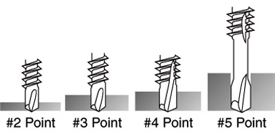
The self-drilling point style requires more consideration due to the variety of thicknesses and possibility of multiple layers being joined. Self-drilling point styles and drilling capacities are defined in the Society of Automotive Engineers (SAE), J-78 document for Self-Drilling Tapping Screws. This document sets minimum requirements for the self-drilling screw design.
Self-drilling point styles are listed as #2, #3, #4 and #5. The higher the number, the thicker material the screw is designed to drill.
Diameter and length
Two dimensions on the drill point govern the ultimate design values of the connection. They are the outside diameter of the drill flute and the length of the drill flute. The thicker the material you want to drill, the longer and wider the drill flute should be. This is when the manufacturer’s drill capacity recommendations become important. Not all self-drilling screw designs are the same.Let’s say you are using a standard 12 diameter #3 point drill screw to attach two pieces of 20-gauge steel. The manufacturer’s recommended drill capacity of this screw is from .100-inch to .175-inch thick. Two pieces of 20-gauge total approximately .066 inch.
You would find that the point drills a hole so large that the thread cannot perform its clinching function. You will easily strip your connection and often the screw will fall out of the hole. The drill point of this screw is too large for the application. The reverse happens if you try to use a fastener with the drill capacity smaller than the total thickness you are fastening. The screw will stop drilling and get stuck in the steel; you will twist off the head of the screw. Following the manufacturer’s recommendations will eliminate these problems.
Looking at the three basic parts of the fastener you will note that a change to any of these parts results in a change to the design capability of the fastener. If you have a flat head sharp point screw and change the point to a drill point you now have a fastener that would not be recommended for wood-to-wood connection but for attachment of wood to steel. If this drill point was used in a wood-to-wood connection, the drill point would ream out the wood and the thread would not hold. You would then have a stripped connection.
Other considerations in your choice of fastener should include body diameter, length and plating or coatings. In a non-load-bearing connection, a #6 body diameter screw can be used. An example may be an electrical box or a plumbing clip fastened to a 25-gauge steel stud. The minimum requirement for a load-bearing connection is a #8 body diameter screw.
The length of the fastener in a connection is determined by the total thickness of all the materials being joined with a minimum of three threads exposed beyond the steel connection.
All fasteners must have a corrosion-resistant coating or plating. The coating or plating may be phosphate, zinc or a proprietary material. Geographic areas may affect the minimum corrosion resistance requirements.
The selection of threaded fasteners has grown over the years with the increased use and recognition of cold-formed steel framing. For many years, the use of threaded fasteners was limited to drywall attachment to 25-gauge steel framing. Recent advancements in design, materials and codes and standards have increased the widespread usage of threaded fasteners in the wall and ceiling industry.
My bet is we will continue to see new and innovative advancements in fastening technologies grow by leaps and bounds.
Looking for a reprint of this article?
From high-res PDFs to custom plaques, order your copy today!


