Referencing Techniques: Schematic Height Diagram
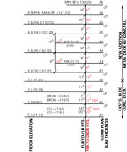
To begin the process of preparing a height diagram, the most important ingredient is the source of information. In most if not all cases, this should be a building section or elevation, preferably a section. Such drawings normally include all the floors with the floor-to-floor heights given. On the example, I made a note at the top to “Reference Building Section Drawing A7.” This was the source for my information for this diagram—it was a North-South Transverse Building Section.
As I stated, normally the architect denotes the floor-to-floor heights on the building section/elevation but in this case, he did not. Thus, I was required to determine these heights on my own from the floor height datum (actual height above sea level) given for each floor on the building section. This required simple but careful differential subtraction using my calculator.
Note that the first floor has two datum (+27.67 and +31.67). This is due to the fact that the lobby area is at a higher elevation (+31.67). I must consider this and include it on the height diagram since I must distinguish between varying heights—even those occurring on the same floor. This affects the cellar floor heights, as well, even though the cellar slab is constant at+11.16 (the slab above determines the height). The first floor datum of +27.67 is the typical elevation for the first floor, so I denote it (typ) on the first floor datum (from +27.67) and on the cellar level (to +27.67). This is relevant and worth noting on the diagram.
Taking the next step
Having determined my floor-to-floor heights, I must now determine the floor-to-deck (underside) heights. These are the working heights and have the most relevance. To emphasize their importance, I use a red pen to list them. To establish these heights, I must first determine overall slab thickness (and type). Typically, as in this case, this information is found on larger scale wall sections and details. This building had two slab thicknesses: a solid concrete slab 6 inches thick for the existing (cellar to third) and a new metal deck with concrete fill for the new addition (third through the roof).The overall thickness for the new deck is 21⁄2 inches but I use 3 inches as the thickness rather than 2 or 21⁄2 inches. This rounding up is standard, being more conservative, and whole feet and inches are much easier to work with. You will notice that I made a reference line on the right side of the diagram showing the extent of the existing building/new addition and described the slab condition. This simple reference proved extremely helpful during the course of the quantity survey. Important as the heights are, it is also critical to have advance knowledge of the type of structural system you will be anchoring to and/or hanging from.
As I established the slab thicknesses, I listed them on the right side of the diagram below the floor line. By simply subtracting the floor-to-floor height from the overall slab thickness, I easily determined the floor-to-deck heights. At this point, it is worth a brief discussion of the importance of decimal equivalents. A calculator does not recognize 11 feet, 9 inches—it recognizes 11.75 instead (0.75 being the decimal equivalent of 9 inches). Thus, to simplify addition, subtraction, multiplication, division, etc., you must work with and be familiar with the decimal equivalents, from 1 through 11 inches.
You can never be too sure
By now, I know these by heart but I still sometimes get confused with the odd numbers such as 5 inches (0.41) or 7 inches (0.58). To make it a no-brainer, long ago I typed these equivalents on a small piece of paper and taped them to my calculator (they are still there and I suggest you do the same). For example, to establish the floor-to-deck height for the third floor, I simply subtracted 0.25 (3 inches) from 11.75 (11 feet, 9 inches) and established 11 feet, 6 inches as the floor-to-deck height. Decimal equivalents are easily established by dividing the inch (numerator) by 12 (denominator).For example: to establish the 4-inch decimal equivalent, 4 inches/12 inches = 0.33. Note that although floors two and three have the same floor-to-floor height, they have different floor-to-deck heights due to a difference of slab thickness/type.
Had the floor-to-deck heights for floors two and three been the same, I would have made one line for them to save space. I could have done this for floors 4/5 and 4M/5M but I did not since these are the duplex floors (lower and upper) and it was easier to understand the diagram if I kept them separate and there was sufficient room to do so. Note the abbreviations LDX (lower duplex) for floors 4/5 and UDX (upper duplex) for floors 4M/5M.
Because there are areas open to above on floors four and five and open to below for floors 4M and 5M, I included a separate height axis (to the left) from the main axis to distinguish the double height nature of the duplex units where they are open to above/below. This double-height axis follows the same scheme as the main axis: floor-to-floor heights on the left, floor-to-deck heights on the right (in red). Though the sixth and seventh floors are the lower/upper penthouse floors (LPH/UPH respectively), they do not require a separate double height axis because these floors do not have the same open to above/below conditions as do the duplex floors. As an additional reference, I included on the right side of the diagram the drawing number on which the floor plan could be found.
Placed in plain view on the bulletin board adjoining my table, all the pertinent information concerning the nature of the heights, slab thickness/type, extent of existing building/new addition, datum elevations and floor plan reference is at my effortless disposal for the duration of the quantity survey/cost analysis. Also, it plays a big part in the familiarization process whereby the complexities of the building’s structural system, layout of floors, heights, etc., really begin to unravel and become understood. It is also important for understanding the floor loading conditions that will be encountered.
It is best to use lined paper and a straight edge to draw the lines. Next month, I discuss another important schematic used for referencing—a schedule schematic. It too, like the schematic height diagram, is an important tool in the estimator’s toolbox.
Looking for a reprint of this article?
From high-res PDFs to custom plaques, order your copy today!


