Beneath the Surface of the Sphere
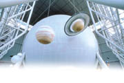
Architects at Polshek Partnership, New York, placed the Sphere inside a glass cube adjacent to Central Park. As the highly visible centerpiece of the Rose Center, the Sphere had to be visually flawless in its execution. The 87-foot-diameter Sphere houses the new Hayden Planetarium and Big Bang Theater and is clad with 2,474 perforated light-gauge metal panels. Panels had to be formed with a spherical curvature and configured to adjust for changes in latitude.
To maintain visual alignment, the locations of 5,599,663 slotted perforations had to be individually calculated and positioned. The Sphere had to be acoustically absorbent to attenuate the noise produced by thousands of visitors inside the glass-walled building. And the work had to be accomplished within a down-to-earth budget and construction schedule.
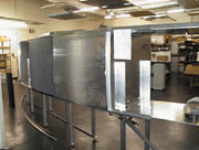
Working for construction manager Morse Diesel International Inc. (now known as AMEC Inc.), New York, the Sphere’s cladding was designed and fabricated by Ceilings Plus, a Los Angeles manufacturer of specialty ceilings, and installed by interiors and specialty contractor Island ADC Inc., of Holtsville, N.Y. While curved acoustical panels are increasingly popular, the Sphere is one of the first attempts to use perforated metal panels curved in two axes simultaneously.
The computer-aided-design and -manufacturing techniques used to make the Sphere may indicate the trajectory of future architectural metalwork.
“CAD/CAM makes it possible for us to fabricate panels in almost any shape,” says Nancy Mercolino, president of Ceilings Plus. “If you can draw it, we can probably make it. While there will always be a need for traditional metal forming arts, our automated equipment enables us to fabricate customized metal panels for about the same cost as standard products.”
Complex geometry of a simple form
The Sphere required astronomical computational power to solve the geometric problem of transforming flat sheet metal into three-dimensional, doubly curved panels. None of the panels, for example, had straight edges. Instead, each sheet of aluminum had to be cut with precisely calculated curved edges that corresponded to circular lines of longitude and latitude and allowed for the stretch forming of the flat metal into spherical segments.Two sets of curved aluminum angles also had to be calculated and formed. One set was welded to the panels to stiffen the panel edges; the other was attached to the Sphere’s structural steel armature to provide a sub-framing system. Except at the equator of the Sphere, the corners of the aluminum angles did not meet at simple right angles. Instead, they had to be cut and assembled so that they intersected along imaginary lines radiating out from the center of the Sphere.
An even more daunting set of calculations was the exact positioning of more than 5.5 million slotted perforations. Since the perforations are along lines of latitude, the slots had to be laid out in curved arrays and uniformly spaced to avoid visually distracting patterns. In addition, the lengths of the perforations along the panel sides had to be modified to maintain a uniform 11/16-inch border along each panel edge. In total, more than 11 million data points had to be determined to control the placement of the perforations.
Furthermore, the platonic purity of the Sphere was interrupted by bridges providing visitors and utilities with access to the Planetarium, and by three pairs of skewed legs that hold the Sphere aloft. None of the penetrations were perpendicular to the surface of the Sphere and conventional extrusions could not be satisfactorily bent into the complex curvatures required for trim. Ceilings Plus chose, instead, to carve the trim members from solid blocks of aluminum using five-axis computer numerically controlled milling equipment originally developed to build spacecraft.
Fabricating the Sphere’s cladding
While it would have been possible to design and fabricate the Sphere’s cladding without computers, Ceilings Plus designer Gary Kawamura says the work would probably have taken five to 10 times longer to complete. Ceilings Plus produced more than 150 sheets of highly detailed CAD shop and erection drawings. To expedite the project, the drawings were transmitted between Los Angeles and New York via e-mail. After approval, the computerized drawing were converted into CAD/CAM files and used to control sophisticated CNC equipment to cut and perforate the aluminum. Each panel was then gently stretch-formed into a spherical segment and welded to curved aluminum stiffeners.
The final fabrication step was to factory-apply a non-woven acoustical fabric to the inside surface of each panel. The acoustical fabric was a specially made shade of light gray selected by the architect to achieve the desired visual effect. Al Kichell, Ceilings Plus chief engineer, explains that with approximately 30 percent open area, the perforated metal allowed noise in the Rose Center to pass through the panels so it could be dampened in the cavity between the inner and outer walls of the Sphere. In conjunction with spray-applied fireproofing used to give the Sphere a two-hour fire resistance rating, the panel system provided an NRC-90 noise reduction coefficient.
Construction schedules and tolerances
Accumulated tolerances in the Sphere’s superstructure put the structural steel out of position by as much as an inch or more. The cladding system, however, allowed almost no tolerance for dimensional errors. For example, a variation of only 1/32 inch per panel could have added up to a gap or overlap more than 2 inches wide once the error had been repeated all the way around the Sphere. Fortunately, the CNC processes used by Ceilings Plus allowed the company to manufacture panels with tolerances measured in 0.005 inch.As the first step in assembly, Island and Morse Diesel surveyed the structure to locate the Sphere’s axis and establish control points.
“Layout was the hardest part of the job,” says Matt Stevens, Island project manager. “The structural steel was more like an egg than a sphere, and we had to install the sub-framing system to form a nearly perfect sphere.”
Island installed curved aluminum angles horizontally around the structural steel. The angles were mounted on specially designed brackets that could be adjusted in every direction, and sophisticated three-dimensional surveying techniques were used to ensure that the sub-framing was precisely positioned. A grid of curved, cruciform aluminum extrusions was then erected to define lines of longitude and latitude and create subtle reveals between panels.
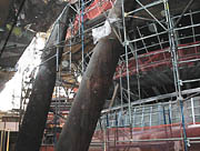
According to Morse Diesel project manager Jerry Maffia, meeting the required tolerances was especially challenging because only 7 inches of clearance existed between the surface of the Sphere and the superstructure members.
“There was no give and take on the diameter of the Sphere,” he says.
Another erection challenge was providing access to all areas of the Sphere.
According to Stevens, “In some areas we were working overhead like on a ceiling, in other areas, it was like working on a wall, and in other areas, we were working below our feet.”
Scaffolding had to be erected on top of the spiraling ramp that connected the Rose Center’s first and second floors. Near the Sphere’s “north pole,” portions had to be cantilevered and supported from the roof structure.
Still, says Stevens, “There were areas we could only reach by putting on harnesses and climbing the steel.”
The panels’ compound curvature gave the panels inherent strength and rigidity despite the thin, 0.063-inch aluminum used, and perforations made the panels even lighter. Their light weight was important since most panels had to be hand carried up the scaffolding.
Ceilings Plus provided concealed torsion spring clips that allowed panels to be snapped onto the cruciform grid and removed for access to the cavity behind the panels.
Mercolino says the springs were critical to the success of the project.
"The force required to install or remove panels with conventional friction fit or clamp mounting systems can loosen connections and deform panels,” she says. “We used torsion springs instead because they will provide better value over the life of the project.”
Torsion springs, she adds, “put the panels under the jurisdiction of the carpenters, whom we knew could work within the tolerances the Sphere required.”
“I was concerned about using the torsion springs initially, but snapping the panels into place proved to be the easy part," says Richard Wolkowitz, Morse Diesel senior project manager. He says the springs have not loosened over time, and that they simplified repair or replacement when several panels were damaged during construction.
Pushing the limits
The techniques employed to create the Sphere could represent a new universe of opportunities opening for architects and ceiling contractors.“The geometry of the Rose Center Sphere pushed us to the outer limits of our computational and panel fabrication capabilities,” says Mercolino. “But since then, we’ve already been asked to fabricate even more complex shapes. Once architects understand what we can do, it frees their imaginations to create even more out-of-this-world designs.”
Looking for a reprint of this article?
From high-res PDFs to custom plaques, order your copy today!


