The Bridge
Referencing Techniques: Wall-Type Schematic Schedule (Part 4)

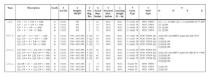
This month, we conclude our on-going discussion of the use and application of a wall-type schematic schedule with an in-depth discussion of an actual example of a schematic schedule based on the sample wall-type series discussed last month. In addition to the table below, please refer to last month's charts or visit www.wconline.com for the complete visual aid.
I like to use sheets that are 11-inch-by-17-inch--with 40 rows and 13 numbered columns and a 2-inch-wide column at the left-hand side. I find this size works best since it can record a lot of data. The very first column records the type designation given the wall by the architect's schedule. It is indicated on the floor plan(s) as a tag or target identifying the various wall types. In this case, types <3>, <3.1> and <3.2> all had four variations whereby the stud size differed. Wall type <3.3> had only three variations--it did not include 1 5/8-inch framing (see stud sizing chart). However, it did include 2 1/2-, 4- and 6-inch framing as did <3> through <3.2>. What is unusual here is the fact that all standard C-stud framing sizes are present except for 3 5/8 inch. This is unusual since 3 5/8 inch has become widely used--particularly for partition wall assemblies. Note that I placed a number (1 or 2) in lower case at the right side of the target. This lets me know whether or not the wall is fire rated (1-or 2-hour typical).
Sorting apples from oranges
The second column is 2 inches wide and I use it to describe the wall assembly--it is titled "description" in the heading. I use the board and stud size (in inches) and record this information from left to right--just as it appears on the architect's schedule. When repetition occurs such as for the board size, I sometimes use a down-pointing arrow to note that the same item/condition occurs in the proceeding assembly as did in the preceding. This happens quite often--in all categories. The need for a sound attenuation blanket is determined by the presence of a lower case "s" adjacent to the wall-type target on the plan(s). Thus, each assembly can be with or without an SAB--dependent on this indicator. To acknowledge this condition, I use the symbol for plus or minus. When two or more layers of gypsum board occur on one or both sides of the framing, I save space by indicating it thus: (2)L 5/8.The thin column next to the description column I use to indicate the number of beads of acoustical caulking/sealant. In this case, all assemblies had four--one on each side of the wall, top and bottom. Column number 1 denotes the gauge and spacing (OC) of the framing. The architect did not define the GA/OC on the schedule description so I must determine this for myself by investigating the specifications, details and/or manufacturer's limiting height criteria. To highlight this situation, I record "to be determined" (TBD) in this column/row(s) for all assemblies.
Column number 2 records the generic height of the framing and board. I need not note the insulation's height since it is a function of the board height and typically extends the same height as the board. Acoustical insulation (SAB/SAFB) works in conjunction with gypsum-board panels based on the board thickness (1/2- or 5/8-inch typical) and the number of layers of board, as well as the insulation's thickness. The sound transmission coefficient achieved by a particular assembly is based on this. If a wall is fire rated, I know automatically that the framing and board must extend to the underside of the structural deck or full height. For types <3.1> and <3.2>, additional layers on one or both sides of the wall (for sound attenuating purposes) extend to 3 inches above finish ceiling. Thus, I note this in the column and explain it further in the "Notes" column. I use four categories for this column typically:
FH ~ Full Height
AFC ~ Above Finish Ceiling
UFC ~ Underside of Finish Ceiling
LW ~ Low Wall
Of course, FH and AFC are most common.
CYA or else!
Column 3 records the fire rating achieved by the wall in hours. As discussed last month, there was ambiguity concerning whether or not wall types <3.1> and <3.2> are one-hour rated (I suspect they are not). Based on the CYA principle of estimating, we will consider them to be rated and the bracketed letter "Q" indicates the need to qualify and clarify this in our formal proposal. Columns 5 and 6 indicate the actual wall thickness dimension. In this case, the stud-sizing chart indicated (last month's on page 54) only the actual dimension(s) and they are recorded on the schematic. No mention is made regarding the nominal wall thickness dimension(s) thus, this is indicated "N/G" (not given) on the schematic. I would assume that the architect uses the actual dimension on the plans--or none at all. Likewise, there is no reference to limiting heights typically used to define GA/OC and it is also noted "N/G" in all rows for all assemblies.Column 7 indicates the insulation type. Having a separate column saves space in the description column where it is generically described (SAB/SAFB for acoustical insulation/BATT for thermal insulation). Wall types <3> through <3.2> are one-hour rated and require a 1 1/2-inch thick SAB (per schedule) which is typically the Thermafiber brand. Type <3.3> is two-hour rated and, as per the schedule, requires a 3-inch SAB, also Thermafiber. I will verify the insulation type by a review of the specification for building insulation.
Basically, I use four distinctions to abbreviate insulation type for this category/column:
TF ~ Thermafiber (SAB/SAFB:acoustical)
FG ~ Fiberglas (SAB/SAFB: acoustical)
FFFG ~ Foil-Faced Fiberglas Batt thermal)
SRFG ~ Semi-Rigid Fiberglas (thermal)
Column 8 generically describes the wall type. In this case, they are all rated partitions. Column 9 is reserved for numbered notes as they occur/re-occur. Note 1 refers to the requirement for an SAB. Note 2 refers to the need for "Lead-Lining to 7 feet, 0 inches above finish floor." Most likely, there is radiology (x-ray) equipment in this building that requires lead shielding in the walls. Notes 3 and 4 refer to the additional layer(s) on one or both sides of the wall assembly (to 0 feet, 3 inches AFC). When a note re-occurs, rather than re-write it, I place the letters DO (ditto) next to the note number(s) applicable to indicate the same note(s) as previously described apply to this row/assembly.
Other categories can occur on a wall-type series, including an Underwriters Laboratory listing/number for the assembly or an STC rating. Neither of these occurred here so they were not categorized in the heading to save space. In New York City, there is often a Board of Standard & Appeals number listed for fire-rated assemblies. The BSA is a regulatory agency that governs the use and application of many of the constructed elements of a building in New York City--including rated walls.
For our example, we only dealt with one type of wall series. Considering that there were probably 15 or 20 wall types/series for this job, you can begin to see the value and need of the schematic. It is readily available for reference and is invaluable to the quantity survey/costing phases of the estimate--as we shall discuss in future columns. Next time, we continue our discussion of referencing techniques with an in-depth look at the usefulness of profiling.
Looking for a reprint of this article?
From high-res PDFs to custom plaques, order your copy today!


