All Things Gypsum: Using a Gypsum Board Membrane System for Fire Resistance
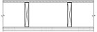
One Hour Ceiling (Based on GA file Numbers FC 5406 and RC 2601)
Most of us are familiar with the terms “fire barrier” or “party wall.” These are fire-resistance-rated assemblies that separate two or more distinct areas in a building. Likewise, there are many fire-resistance-rated floor/ceiling systems that are used to prevent the spread of fire from one story of a building to the next. Such assemblies and many other fire-resistance-rated systems can be easily constructed using gypsum board. Designs for these assemblies can be found in the Gypsum Association’s “GA-600, Fire Resistance Design Manual,” the UL Fire Resistance Directory and other sources.
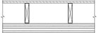
Two-Hour Ceiling (Based on UL Design L556)
When is the use of a membrane system appropriate?
However, it is often the case in retrofit work and occasionally in new
construction that no fire-resistance-rated assembly exists to properly match a
building’s configuration. In such situations, a gypsum board “membrane,” usually
constructed with multiple layers of type-X gypsum board, can provide all the
required fire resistance. This principle of using a gypsum membrane for fire
resistance relies on the concept of the “finish rating.”
A finish rating is derived from the same test method (ASTM E 119) that is used to determine the fire-resistance ratings of systems. The finish rating is the time necessary for an average rise in temperature of 250 degrees F or a maximum rise of 325 degrees F as measured on the face of the framing member nearest the test fire. In a gypsum board system, this is the time required for the back (unexposed) surface of the gypsum board to reach one of the limiting conditions as defined above.
Most fire-resistance-rated systems with combustible (i.e., wood) framing components have finish ratings. In gypsum board construction, the finish rating can be determined to be the fire-resistance rating provided by the gypsum board membrane on the fire-exposed side. While the use of a finish rating to meet fire-resistance requirements is a common and generally accepted practice to validate and document the required fire resistance of a membrane, its use must be approved by the authority having jurisdiction.
Over the years, hundreds of fire tests have been conducted on fully loaded floor/ceiling systems that were built with solid-sawn wood 2x10 floor framing. However, most of these tests were conducted prior to the development of engineered wood trusses, wood I-joists and lightweight steel joists. Using modern construction methods, in which engineered systems that are designed using calculations that factor in the actual loads and spans, specifiers can create systems that do not require 2x10 joists. These engineered systems commonly use smaller dimensional lumber, wood-I trusses, other engineered lumber products, steel channel joists, or other materials for the structural framing.
The effect of using smaller lumber sizes and engineered lumber products where shorter spans and lower loads are encountered is difficult to document using full-scale fire tests due to the large size of the test specimen required by the ASTM E 119 fire test method. Consequently, it may not be possible to evaluate such designs by full scale tests.
Additionally, in retrofit construction, designers, contractors, and building officials frequently confront unique situations that require innovative solutions. Modernizing existing building systems often involves working in existing areas that provide limited access or requires the integration of existing construction materials for which there is currently no available tested or listed system. When there is no tested system that suits a particular situation or condition, the use of the finish rating of a system may be the only practical means to achieve the desired fire-resistance rating.
The gypsum board membrane configurations most commonly used to meet fire-resistance requirements in unique circumstances are described and shown in the graphics listed in this column. The details and sketches are based on UL Designs U301 and L556 and on GA File Numbers FC 5406 and RC 2601.
The one-hour ceiling membrane consists of two layers of 5/8-inch type X gypsum board attached directly to the ceiling framing or furring. Both layers of gypsum board are applied perpendicular to framing members spaced not more than 24 inches on center. The base layer is attached with 1-inch Type S or S-12 drywall screws to steel framing or 1¼-inch Type W or S drywall screws to wood framing with all screws spaced at not more than 24 inches on center. The face layer is applied to the framing with 15⁄8-inch Type S or S-12 drywall screws for steel framing or 17⁄8-inch Type W or S drywall screws for wood framing spaced 12 inches on center at joint ends and intermediate joists. In addition, 1½-inch Type G drywall screws, are installed at 12 inches on center in a row parallel to and 2 inches from each side of end joints. Joints of the face layer are offset 24 inches from the joints in the base layer and all joints and fasteners are finished to Level 1 as specified in “GA-214, Levels of Gypsum Board Finish.”
The two-hour ceiling membrane consists of four layers of 5/8-inch type X gypsum board applied to ceiling framing spaced 24 inches on center with a 7/8-inch hat-shaped steel furring channel located between the third and face layer. The base layer of gypsum board is applied perpendicular to the ceiling framing and attached with 1¼-inch Type S or W drywall screws spaced 12 inches on center. The second layer of gypsum board is applied perpendicular to and attached to the ceiling framing with 2-inch Type S or W drywall screws spaced 12 inches on center. The third layer of gypsum board is applied perpendicular to the ceiling framing and attached with 2½-inch Type S or W drywall screws spaced 12 inches on center. The joints in each layer are offset a minimum of 10 inches from the previous layer.
The steel hat-shaped rigid furring channels are applied perpendicular to the ceiling framing and spaced 24 inches on center. The channels are attached to the ceiling framing at each framing member/furring channel intersection with two 2½-inch Type S or W drywall screws. The face layer of gypsum board is applied perpendicular to the furring channels and attached with 11⁄8-inch Type S drywall screws spaced 12 inches on center. Face layer joints and fasteners are finished to Level 1 as specified in “GA-214, Levels of Gypsum Board Finish.”
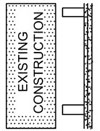
The one-hour wall membrane consists of two layers of 5/8-inch type X gypsum board applied directly to the wall framing or furring. The base layer of gypsum board is applied either parallel or perpendicular to wall or partition framing members spaced not more than 16 inches on center and is attached with 1-inch Type S or S-12 drywall screws to steel framing, or 17⁄8-inch nails or 1¼-inch Type W or S drywall screws to wood framing. Base layer fasteners are spaced 6 inches on center. The face layer is applied either parallel or perpendicular to the framing and is attached with 15⁄8-inch Type S or S-12 screws to steel framing, or 23⁄8-inch nails or 17⁄8-inch Type W or S screws for wood framing. Face layer fasteners are spaced 8 inches on center. Joints of the face layer are offset 24 inches from the joints in the base layer. Face layer joints and fasteners are finished to Level 1 as specified in “GA-214, Levels of Gypsum Board Finish.”
Best practice dictates that a fully fire tested system be incorporated into building construction whenever possible. However, as pointed out above, sometimes solving a specific circumstance requires the use of a derived or calculated fire-resistive membrane or system. The use of such systems is not unique to gypsum board, as many assemblies that incorporate other building materials such as concrete, masonry, or steel are calculated or derived based on accepted formulas. Membrane systems have a place in modern construction and they should be used judiciously. For additional information, download a copy of “GA-610, Fire Resistance Provided by Gypsum Board Membrane Protection,” from the Gypsum Association’s Web site at www.gypsum.org.
In the September column of All Things Gypsum, we used a graphic to illustrate a double row of steel studs with a single layer of gypsum board that achieves a one-hour fire-resistance rating and a 50 to 54 STC rating. That design requires 3½ inches of glass fiber insulation that unfortunately did not appear in the graphic. For a correct depiction of that assembly, go to our Web site at www.gypsum.org/GA60006.html. Choose either the low-resolution version of GA-600-06, or division 2 of the high-resolution version. On page 28 of the manual, you will find GA File Number 1024, which displays the correct graphic.
When is the use of a membrane system appropriate?
Test Body Copy for delete
Test Body Copy for deleteTest Body Copy for deleteTest Body Copy for deleteTest Body Copy for deleteTest Body Copy for deleteTest Body Copy for deleteTest Body Copy for deleteTest Body Copy for deleteTest Body Copy for deleteTest Body Copy for deleteTest Body Copy for deleteTest Body Copy for deleteTest Body Copy for deleteTest Body Copy for deleteTest Body Copy for deleteTest Body Copy for deleteTest Body Copy for delete
Looking for a reprint of this article?
From high-res PDFs to custom plaques, order your copy today!


