Big Leaks in Small Spaces
Water leakage through building walls continues to be the single largest cause for construction litigation in new buildings. The root of most water penetration problems is the lack of integration and coordination between the waterproofing elements of the various components within wall assemblies.
Water leakage through building walls continues to be the single largest cause for construction litigation in new buildings. Litigation is all too often a long, tedious, expensive and unpredictable venture for owners and building managers. The litigation process often delays repair efforts which can exacerbate damage to finishes and building content, and, more importantly, the structure of the wall assembly. Loss of use of the workspace inevitably creates tensions and economic issues between managers/owners and the tenants that occupy their buildings.
This fact is illustrated by the following case study. The building is a recently constructed steel-framed structure in the Midwest. Shortly after occupancy of the building, the building manager received tenant complaints of leakage through the curtain walls, which caused damage to interior gypsum drywall finishes and formed large puddles of water on various floor levels throughout the building. The manager noted that the damage and leakage appeared to be associated with curtain wall sills. We were brought in by the building owner to investigate the cause for the curtain wall leakage after attempts by the curtain wall installation contractor failed to correct the problems. The façade for this building is composed of multi-story metal and glass curtain walls, with veneer brick masonry and cast stone over steel stud back-up walls.
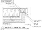
 The curtain wall jamb and sill flashing details are illustrated in Figures 1 and 2, respectively; the masonry wall detail is also illustrated in Figure 1. In Figure 1 we see that the designer provided a membrane flashing attached to the side of the vertical curtain wall frame that extends behind the masonry veneer and integrates with the building felt water barrier outboard of the steel stud back-up wall. We also see that the designer developed a drained cavity wall system with a bituminous felt water barrier.
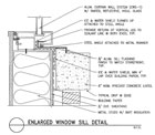
In Figure 2, we see that the designer also developed a multi-layered sill flashing and waterproofing detail that extends out over the cast stone sill below and turns up beneath the curtain wall sill to collect any water that may enter through or around the curtain wall at this level.
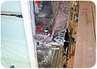
 Figure 3 shows one means of accomplishing continuity at the curtain wall sill-to-masonry wall flashing transition.
Most designers understand the fundamental principles of waterproofing and ways to keep water out of their buildings. Contractors likewise know the importance of proper execution of those details and the methods for keeping the buildings they build watertight. So, why do both of these professionals seemingly overlook the fundamental issues of coordination and integration between wall system components? To answer this question, we first need to understand the differences in the design and construction processes from the perspective of the designer and contractor.
Both the design and construction processes are complex work efforts. The designer is typically retained by the owner, a developer, or sometimes a builder, to prepare drawings for the construction of a building. Designers usually accept a fixed fee for their work to develop a concept for a building and then to transform that concept into a set of comprehensive documents that can be followed by a contractor, like a road map, through the construction process.
The designer is not only interested in the building envelope, but must also develop detailed drawings for floor layouts, mechanical and electrical systems and controls, plumbing, interior finishes, landscaping, parking lots, site drainage as well as any specialty systems specific to the owner’s use of the building. With so much effort going into so many aspects of a design, many designers limit their efforts on the building envelope systems to selecting materials, establishing typical wall profiles and then developing details for the typical wall systems only.
The general contractor oversees the overall construction of the building and is responsible for coordination and scheduling the various trades and vendors to ensure that a smooth and organized work effort is maintained and that the work stays on schedule and budget. Like the designer, the general contractor generally works within a fixed budget to move the construction effort toward completion. He may spend most of his time coordinating schedules to avoid delays between the various trades. Coordination of transition details between wall components is often passed along to a specialty subcontractor, but this does not always work out for the best. What generally happens is that each trade ends their work at the interface to the next trade’s work and there is little or no overlap or coordination of the waterproofing across the transition between systems; this is the “forgotten spaces” zone where each trade assumes no responsibility for waterproofing continuity.
Common design and construction practices often contribute to water leakage problems as illustrated by the following scenario:
The general contractor is operating under a tight or accelerated construction schedule. To help streamline the envelope work, he chooses to give a portion of the “Miscellaneous Flashings” and “Waterproofing” work to the masonry and curtain wall trades, reasoning that he will save time by not having to coordinate access and time for a waterproofer in those construction sequences. The masons and curtain wall installers reluctantly take on the added work and eventually install their associated waterproofing materials into the building. However, since there are no details provided in the construction documents that show how to overlap or integrate the various waterproofing components, neither trade assumes the responsibility for coordination between the waterproofing elements.
Since the waterproofing components between the masonry and curtain wall differ in composition, the means for joining these materials together within a narrow space, usually 1/2-inch wide or less, is not obvious or a simple task. The trades simply terminate their work (and waterproofing) in these transitional spaces and water leakage (and possibly air leakage) results.
Post-construction solutions to the problem of coordination within these transition spaces are not easy, since these areas are almost always concealed within the wall, thus requiring significant effort to excavate and correct. The notion that there is never enough time (or money) to do things right at the beginning of a project, but always enough to correct the problems later, is all too common. Issues of detail coordination between elements of the exterior building envelope are at the root of many of these problems.
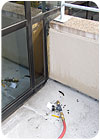
Transitional space detailing and coordination becomes more difficult with the complexity of the building façade. Transitions not only occur between different wall elements, but also occur within components of the same wall assembly, such as the intersecting points of multiple wall surfaces. An example of such a transition is a metal/glass curtain wall terminating above a roof surface as a roof parapet and intersecting at an angle with a rising metal/glass curtain wall. Such a transition may rely on a single line of sealant to maintain waterproofing integrity as shown in Photo 3. Differential movement alone between the two curtain wall surfaces may be enough to cause sealant failure and result in leakage into the building.
While issues of waterproofing coordination are best addressed by the designer during the design development and construction documents phases, they can also be achieved during the construction phase, although the later they are addressed in the construction process, the greater the cost and scheduling implications.
• Require a design review process conducted by a qualified waterproofing consultant. Such a review can help identify areas of waterproofing discontinuity where coordination is likely to be an issue. Design reviews can be implemented not only by the designer, but also by general contractors as a means for helping with performance and scheduling, education of field staff, development of requests for information (RFI’s) to the designer and also as a basis for identifying extra work items not covered by the construction documents.
• Use isometric detailing that shows the transition area and the integration of all waterproofing materials; cross-section details and specifications alone cannot adequately convey the design for waterproofing continuity in the forgotten spaces; an isometric or axonometric is needed. This is the most reliable method for conveying design intent and understanding.
• Require that construction mock-ups include waterproofing details at system transitions. Conduct water tests of completed mock-ups to help verify continuity of waterproofing coverage. Prior to general construction, the details can be fine-tuned and breaches in waterproofing coverage can be identified and addressed.
• Require that the contractor develop isometric details for transition spaces as part of their shop drawing submittal package.
• Require construction monitoring of the work by a qualified waterproofing consultant or inspection agency that is trained to evaluate and identify waterproofing issues. Be present when the work begins.
Failure to address waterproofing continuity in the transitional spaces between system components is not necessarily deliberate, but because it is a major cause for leakage, premature deterioration of building components and finishes, and construction litigation, designers and contractors both need to focus more attention and coordination efforts on these areas.
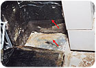
A built flashing detail with the unsealed copper fabric flashing in the masonry wall folded back at the transition between the masonry wall and curtain wall sill. Arrows denote deterioration of the unprotected gypsum sheathing and rusting of the steel stud framing.
Water leakage through building walls continues to be the single largest cause for construction litigation in new buildings. Litigation is all too often a long, tedious, expensive and unpredictable venture for owners and building managers. The litigation process often delays repair efforts which can exacerbate damage to finishes and building content, and, more importantly, the structure of the wall assembly. Loss of use of the workspace inevitably creates tensions and economic issues between managers/owners and the tenants that occupy their buildings.
Figure 1: As designed, masonry-to-curtain wall jamb detail
THE ROOT OF THE PROBLEM
As investigative and design consultants, we see the same types of problems from project to project. The root of most water penetration problems is the lack of integration and coordination between the waterproofing elements of the various components within wall assemblies. This problem exists within the “gray” areas or transition spaces where one building element or wall assembly (such as a window or glass/metal curtain wall) terminates and another building element (such as a masonry wall) begins. Although these transition areas constitute a relatively small surface area of the building wall, they cause the bulk of wall leakage problems.This fact is illustrated by the following case study. The building is a recently constructed steel-framed structure in the Midwest. Shortly after occupancy of the building, the building manager received tenant complaints of leakage through the curtain walls, which caused damage to interior gypsum drywall finishes and formed large puddles of water on various floor levels throughout the building. The manager noted that the damage and leakage appeared to be associated with curtain wall sills. We were brought in by the building owner to investigate the cause for the curtain wall leakage after attempts by the curtain wall installation contractor failed to correct the problems. The façade for this building is composed of multi-story metal and glass curtain walls, with veneer brick masonry and cast stone over steel stud back-up walls.
Figure 2: As designed, curtain wall with metal sill flashing detail
In Figure 2, we see that the designer also developed a multi-layered sill flashing and waterproofing detail that extends out over the cast stone sill below and turns up beneath the curtain wall sill to collect any water that may enter through or around the curtain wall at this level.
Photo 2: Discontinuous flashings at brick relieving angle dead-end against curtain wall. Top arrow points out an open joint in the wall sheathing that leads directly to the interior. Bottom arrow identifies unsealed edge of masonry wall flashing against curtain wall jamb.
GOOD DESIGN, POOR COORDINATION
Through a comprehensive program of isolation water tests and selective probes of the wall system, we discovered that, for the most part, the walls were constructed as detailed by the designer. So what went wrong with a design that incorporates back-up waterproofing protection, drained cavity wall construction and integral flashings? The problems occurred at the transitions from curtain wall flashing to cavity wall flashing. As shown in Photo 1, the point at which all the waterproofing layers within the wall system intersect lacks waterproofing continuity as the transition moves from the masonry wall to the jamb of the curtain wall and results in large voids through which water can flow onto the back-up sheathing and back-up wall stud framing as well as leak into the building. Photo 2 shows that a leakage problem can be exacerbated by the fact that water is directed to these “unfinished” transitions by the masonry wall flashing system which was constructed without panned edges to contain water on top of the flashing and conduct it out of the wall.Figure 3: Integrated design at curtain wall sill at masonry wall interface
Most designers understand the fundamental principles of waterproofing and ways to keep water out of their buildings. Contractors likewise know the importance of proper execution of those details and the methods for keeping the buildings they build watertight. So, why do both of these professionals seemingly overlook the fundamental issues of coordination and integration between wall system components? To answer this question, we first need to understand the differences in the design and construction processes from the perspective of the designer and contractor.
Both the design and construction processes are complex work efforts. The designer is typically retained by the owner, a developer, or sometimes a builder, to prepare drawings for the construction of a building. Designers usually accept a fixed fee for their work to develop a concept for a building and then to transform that concept into a set of comprehensive documents that can be followed by a contractor, like a road map, through the construction process.
The designer is not only interested in the building envelope, but must also develop detailed drawings for floor layouts, mechanical and electrical systems and controls, plumbing, interior finishes, landscaping, parking lots, site drainage as well as any specialty systems specific to the owner’s use of the building. With so much effort going into so many aspects of a design, many designers limit their efforts on the building envelope systems to selecting materials, establishing typical wall profiles and then developing details for the typical wall systems only.
THE BREAKDOWN BEGINS
Designers often leave transition details in the hands of the contractor or they attempt to coordinate system integration during construction. This is where the design process often breaks down. Transition details are a fundamental part of effective wall design and should not be delegated to the contractor during the construction process. These details cannot be treated as being of secondary importance or an afterthought.The general contractor oversees the overall construction of the building and is responsible for coordination and scheduling the various trades and vendors to ensure that a smooth and organized work effort is maintained and that the work stays on schedule and budget. Like the designer, the general contractor generally works within a fixed budget to move the construction effort toward completion. He may spend most of his time coordinating schedules to avoid delays between the various trades. Coordination of transition details between wall components is often passed along to a specialty subcontractor, but this does not always work out for the best. What generally happens is that each trade ends their work at the interface to the next trade’s work and there is little or no overlap or coordination of the waterproofing across the transition between systems; this is the “forgotten spaces” zone where each trade assumes no responsibility for waterproofing continuity.
Common design and construction practices often contribute to water leakage problems as illustrated by the following scenario:
The general contractor is operating under a tight or accelerated construction schedule. To help streamline the envelope work, he chooses to give a portion of the “Miscellaneous Flashings” and “Waterproofing” work to the masonry and curtain wall trades, reasoning that he will save time by not having to coordinate access and time for a waterproofer in those construction sequences. The masons and curtain wall installers reluctantly take on the added work and eventually install their associated waterproofing materials into the building. However, since there are no details provided in the construction documents that show how to overlap or integrate the various waterproofing components, neither trade assumes the responsibility for coordination between the waterproofing elements.
Since the waterproofing components between the masonry and curtain wall differ in composition, the means for joining these materials together within a narrow space, usually 1/2-inch wide or less, is not obvious or a simple task. The trades simply terminate their work (and waterproofing) in these transitional spaces and water leakage (and possibly air leakage) results.
Photo 3: Curtain wall parapet intersecting with rising curtain wall.
LEAKS IN TRANSITIONAL SPACES
What started out as good intentions by both the designer and general contractor have been transformed into segregated blocks of work for a variety of sub-trades with inadequate coordination between them and none of the sub-trades having responsibility for system-to-system integration of waterproofing. Given this scenario (and there are many variations of this theme), it is easy to see how big leakage problems can occur in those small transitional spaces between components of the exterior building walls.Post-construction solutions to the problem of coordination within these transition spaces are not easy, since these areas are almost always concealed within the wall, thus requiring significant effort to excavate and correct. The notion that there is never enough time (or money) to do things right at the beginning of a project, but always enough to correct the problems later, is all too common. Issues of detail coordination between elements of the exterior building envelope are at the root of many of these problems.
Transitional space detailing and coordination becomes more difficult with the complexity of the building façade. Transitions not only occur between different wall elements, but also occur within components of the same wall assembly, such as the intersecting points of multiple wall surfaces. An example of such a transition is a metal/glass curtain wall terminating above a roof surface as a roof parapet and intersecting at an angle with a rising metal/glass curtain wall. Such a transition may rely on a single line of sealant to maintain waterproofing integrity as shown in Photo 3. Differential movement alone between the two curtain wall surfaces may be enough to cause sealant failure and result in leakage into the building.
While issues of waterproofing coordination are best addressed by the designer during the design development and construction documents phases, they can also be achieved during the construction phase, although the later they are addressed in the construction process, the greater the cost and scheduling implications.
USEFUL TOOLS
Below I provide a list of tools that can be used to help improve waterproofing continuity and coordination (listed in no particular order) in the forgotten spaces. Most of these tools are geared for use by the designer during design development, but they can also be used by the general contractor as well, as a means for clarifying his intent based on his understanding of the design documents.• Require a design review process conducted by a qualified waterproofing consultant. Such a review can help identify areas of waterproofing discontinuity where coordination is likely to be an issue. Design reviews can be implemented not only by the designer, but also by general contractors as a means for helping with performance and scheduling, education of field staff, development of requests for information (RFI’s) to the designer and also as a basis for identifying extra work items not covered by the construction documents.
• Use isometric detailing that shows the transition area and the integration of all waterproofing materials; cross-section details and specifications alone cannot adequately convey the design for waterproofing continuity in the forgotten spaces; an isometric or axonometric is needed. This is the most reliable method for conveying design intent and understanding.
• Require that construction mock-ups include waterproofing details at system transitions. Conduct water tests of completed mock-ups to help verify continuity of waterproofing coverage. Prior to general construction, the details can be fine-tuned and breaches in waterproofing coverage can be identified and addressed.
• Require that the contractor develop isometric details for transition spaces as part of their shop drawing submittal package.
• Require construction monitoring of the work by a qualified waterproofing consultant or inspection agency that is trained to evaluate and identify waterproofing issues. Be present when the work begins.
Failure to address waterproofing continuity in the transitional spaces between system components is not necessarily deliberate, but because it is a major cause for leakage, premature deterioration of building components and finishes, and construction litigation, designers and contractors both need to focus more attention and coordination efforts on these areas.
Looking for a reprint of this article?
From high-res PDFs to custom plaques, order your copy today!


