Gypsum Panel Finish Tolerances
ADDRESSING ISSUES WHEN FINISHING DRYWALL IN CERTAIN SETTINGS.
Over the years, the installation of MEP equipment within a wall cavity, backing installed over the face of framing members for the installation of cabinets or other heavy devices, hard-base trim and granite countertops and backsplashes, have created problems for finishing gypsum panels.
It has always been a fact that finishing gypsum board panels results in an inherent build-up of joint compound at the butt-ends of gypsum board, where the ends of the panel have no board recess; at the sides of gypsum board panels, where there is a recessed edge; accessories, such as corner beads and control joint accessories; and/or wherever gypsum compounds are applied to a gypsum panel. This fact is addressed in ASTM C840, Standard Specification for Application and Finishing of Gypsum Board, Section X.7 Levels of Finish, sub-section X7.2, wherein it states:
As part of the gypsum panel finishing process, the abutting gypsum panel seams/joints, fasteners, and accessories must be concealed with fill and finish coats of joint compound. It is not possible to achieve a finish surface that is a flat plane. This gypsum finishing process occurs above the plane of the gypsum panels. Achieving proper concealment involves finishing the joint and fasteners in graduated arcs that minimize recesses, ridges, or both that would otherwise remain visible.
Recognizing that there is an inherent build-up of joint compound that is proud of the surface of the gypsum board, ASTM C840 states, (as does the NWCB), that the joint compounds shall be sanded to provide a smooth transition to the face of the gypsum panels. This is not to be misconstrued as sanding joint compounds to produce a “flat surface.”
Furthermore, ASTM C840 does not establish a maximum or minimum thickness for the joint compound applied to a butt joint, recessed joint, over fasteners or to the flanges of accessories.
At times, even though the specifications reference ASTM C840 for the Application and Finishing of Gypsum Board, the specific project Specification Section 09 2116 Gypsum Board may infer that the referenced ASTM document provides a thickness tolerance for the joint compounds: Feather coats of joint compound so that the camber is maximum 1/32 inch. I have no idea where this tolerance requirement is taken from, but it is not from the referenced document ASTM C840 Standard Specification for the Application and Finishing of Gypsum Board, nor the reference document GA 216 for the Application and Finishing of Gypsum Panel Products or the reference document GA 214 Recommended Levels of Finish for Gypsum Board, Glass Mat and Fiber-Reinforced Gypsum Panels. If a camber tolerance, such as this, shows up in your specifications, it is an arbitrary tolerance that is not recognized or supported by ASTM standards or by the gypsum manufacturers for the finishing of gypsum panels.
Another Dimension
You may also experience another tolerance dimension in your project specification in Section 3.12, where it speaks to tolerances by stating: Maximum Variation of Finished Gypsum Board Surface from True Flatness: 1/8 inch in 10 feet in any direction. Once again, I have no idea where this requirement was taken from, but it is not a tolerance cited in ASTM C840, GA 216 or GA 214. In fact, the only tolerances noted in ASTM C840 related to flatness are cited in Section 6. Substrate, Surface Preparation, where ASTM C840 states: The attachment surface of any framing member shall not vary more than 1/8 inch (3 millimeter) from the faces of adjacent framing members. Or in Subsection 6.5 where it may state: Devices or items attached to framing members, including the fasteners used to attach such devices or items, shall not protrude more than 1/8 inch (3 millimeter) beyond the surface to which the gypsum board is to be applied.
For the most part, the thickness of joint compound, which varies depending on whether the joint compound is applied to the flange of an accessory, a butt joint, recessed joint, control joint or fastener, only becomes an issue when there are devices or materials attached to the face of the framing members that are greater than 1/8 inch, or equipment within the cavity of the wall is such that the gypsum panels cannot lay flat to the face of the framing members.
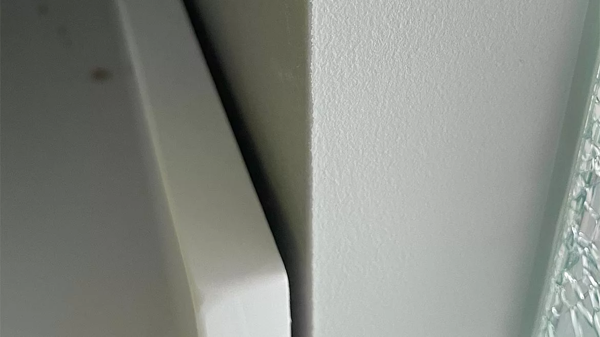
When this becomes an issue, it is generally because of the gap between the gypsum board and a hard surface vanity backsplash or heavy wood base associated with the installation of a corner bead trim accessory. In the following picture, we can see an example of this typical gap. In this case and similar ones, the installation of the corner bead accessory is within industry standards, and the minor gap between the gypsum panel and backsplash is typically filled with a paintable sealant.
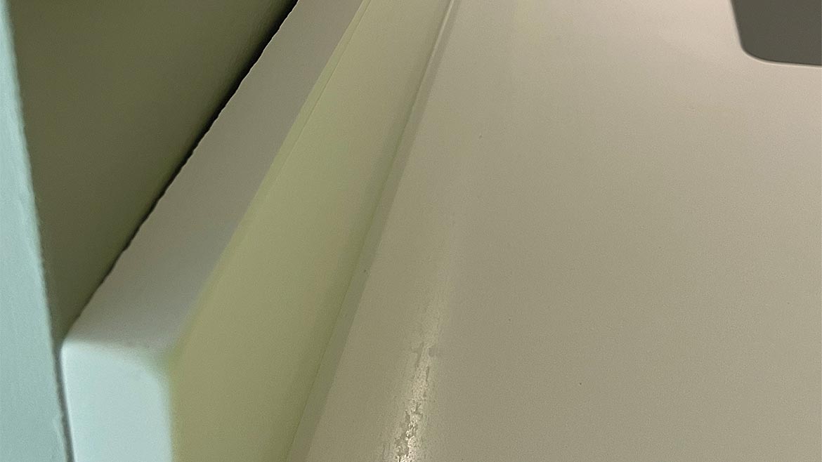 Photo 1
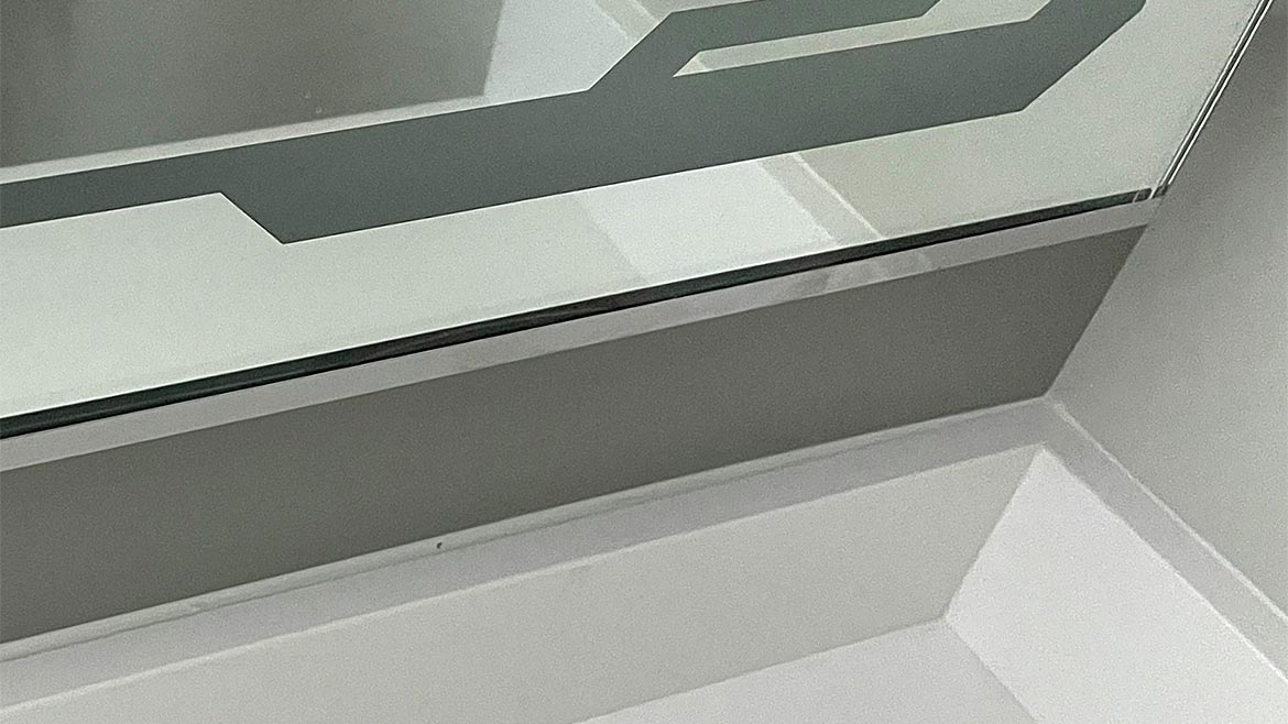 Photo 2
In Photos 1&2, The gap between backsplash and the face of the gypsum panel appears to be typical and within industry standards. The corner bead is attached over the gypsum panel, and successive layers (three) of joint compound are applied over the flange of the corner bead and feathered into the face of the gypsum panel using a 12-inch taping blade. The use of any tool greater in size than the 12-inch blade would not be standard to the industry.
In Photo 3, It is obvious that something within the wall cavity is forcing the gypsum panel away from the face of the framing members and causing the backsplash trim to be forced away from the corner bead. This is most likely, as the picture on the right shows, a combination of MEP equipment within the wall cavity.
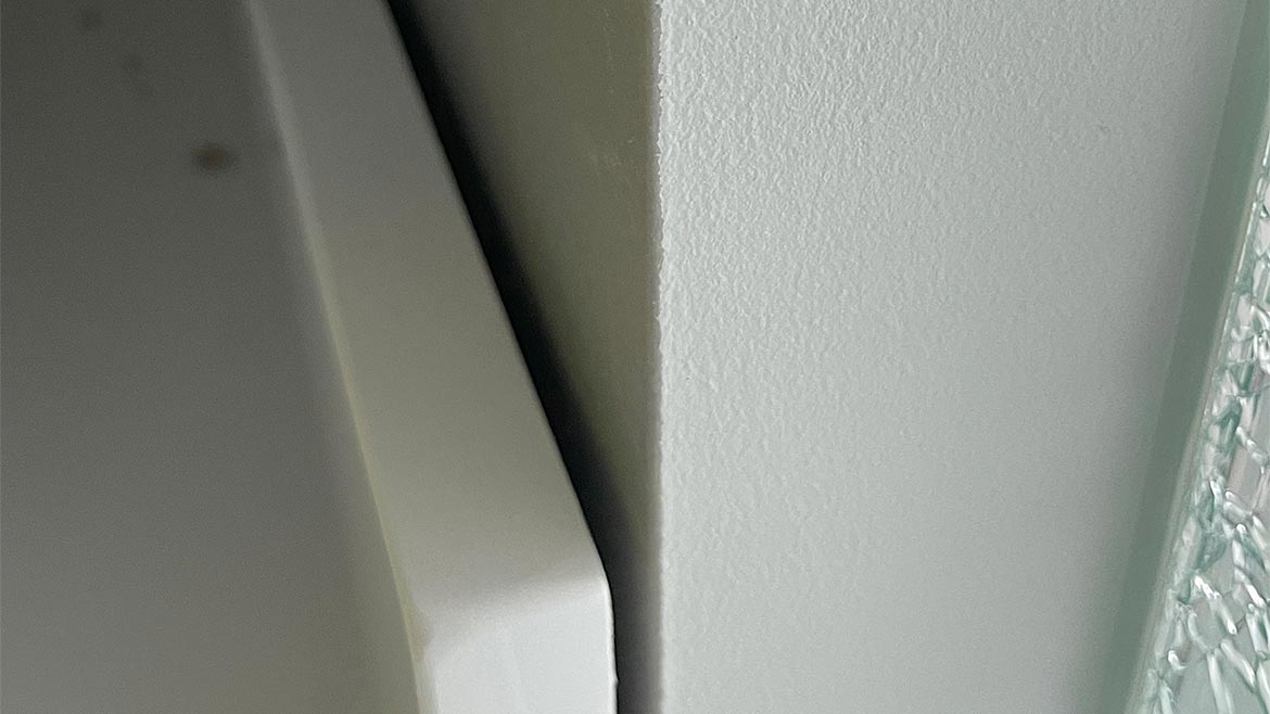 Photo 3
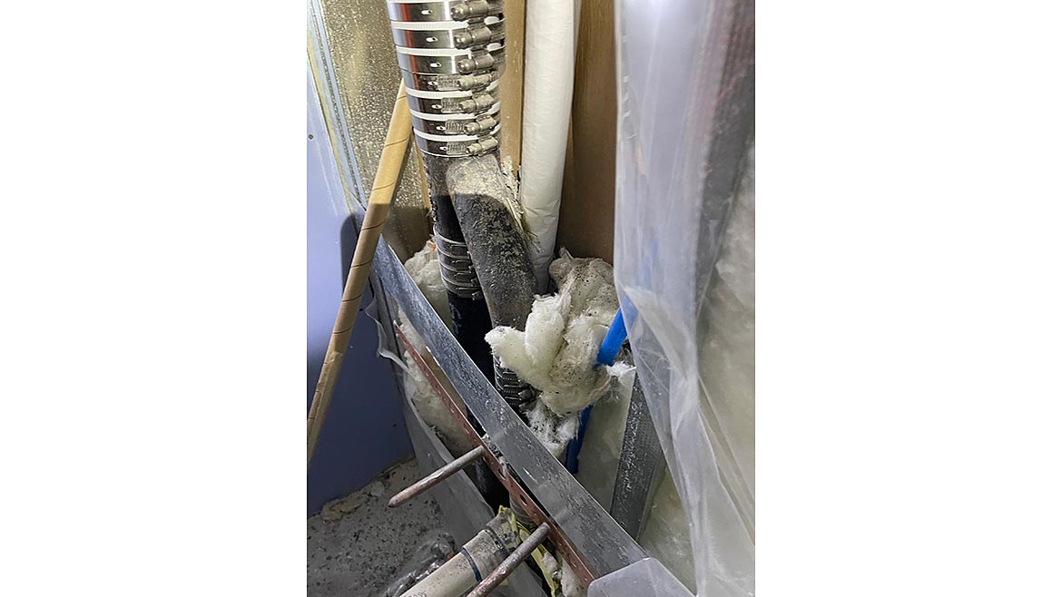 Photo 4
Photo 5
Photo 4
Photo 5
All too often, the NWCB has experienced similar situations where the combination of a multitude of specified MEP equipment is greater than the wall cavity can accommodate. This is not the result of improper framing, drywall installation or finishing but is, in fact, a design issue. Rather than threatening to back-charge the finishing contractor or even the MEP trades for the installation of a combination of MEP equipment, that are, either by themselves or in combination with others, too large for the specified thickness of the wall cavity, back-charges for modifications to the finish to accommodate the bulges from MEP should be the responsibility of the design team.
It is the design team’s responsibility to ensure that the size of the wall cavity is large enough to accommodate all of the specified MEP equipment without damage to, or in this case, distortion of the gypsum panels (as shown in Photo 5).
When it is apparent that MEP installations or other materials are affecting the installation and finishing of gypsum board, the contract between general contractor and subcontractor requires that the subcontractor advise the GC of the unacceptable installation of others materials or conditions. Follow through with an RFI requesting how to proceed, before continuing with the work.
Looking for a reprint of this article?
From high-res PDFs to custom plaques, order your copy today!


