Demystifying the Fly-by Curtainwall Parapet

The pursuit of elegant building enclosure design is ever-growing, particularly for aluminum-framed curtainwall systems. Where these curtainwall systems transition to horizontal roof systems, designers have long sought to minimize the visual impact of these conditions by subtly concealing them. One approach to conceal these transitions from wall to roof is by continuing the curtainwall above the roof line to form a transparent parapet, often referred to as a “fly-by” curtainwall parapet or a “fly-by” parapet (Photo 1).
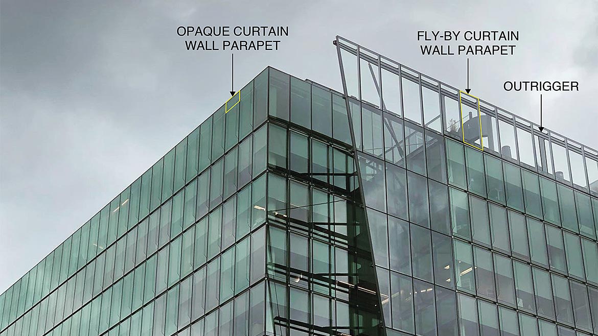 Photo 1 – 1999 K Street NW in Washington, DC with both opaque curtain wall parapets and fly-by curtain wall parapets.
Photo Credit: Image courtesy of Simpson Gumpertz & Heger, Inc. and Oldcastle BuildingEnvelope.
Curtainwall parapets are often opaque, including a spandrel assembly and an inboard curb covered by roof flashings that cap the curtainwall (Figure 1). In contrast, the fly-by curtainwall parapet discussed in this article can incorporate transparent glass, visually consistent with the glass below. The fly-by parapet is achieved by integrating the roofing membrane with the curtainwall near the roof surface, while the vision glass and curtainwall frame continue above. This transparency creates a sleek and often desirable “glass box” effect, where the roof line disappears into the facade and maximizes views at highly visible and activated amenity roof areas while minimizing disruption to the rhythm of the facade.
Design professionals are generally familiar with how to achieve air and water barrier continuity between a roof and a traditional opaque parapet structure. But there is less industry knowledge and guidance regarding design of fly-by parapets, particularly when desiring transparent glazing with limited ability to conceal roofing materials. Designers must approach the fly-by curtainwall feature through selection of appropriate roof and curtainwall systems, regular coordination with the curtainwall and roofing providers, and thorough detailing of the various roof-to-curtainwall transitions.
The sections below explore design considerations, detailing options and techniques to navigate the technical complexities of fly-by curtainwall parapet design with transparent glazing. Other methods of projecting glass above the roof line, such as opaque fly-by parapets and glass balustrades, have their own unique design considerations but are not the focus of this article.
Terminology and Design Considerations
This section describes the typical project conditions where a fly-by curtainwall parapet is incorporated. We also define curtainwall terminology to help contextualize the design options outlined in the following sections.
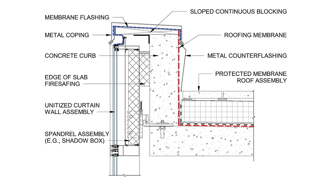 Figure 1 – Example detail for an opaque curtain wall parapet.
Image courtesy of Simpson Gumpertz & Heger, Inc. and Oldcastle BuildingEnvelope.
Assembly Type and Programming
Fly-by curtainwall parapets are typically incorporated on roofs with amenity programming and in a protected membrane roof configuration, in which the insulation and overburden are installed on top of the waterproofing membrane as defined by NRCA (Figure 2.a). The fly-by parapet is often desirable in such applications to minimize visual impediments for occupants at the roof edge, while also providing functional fall protection. For the fly-by parapet to satisfy IBC Section 1015 code requirements for a guard, it must be not less than 42 inches high measured from the adjacent walking surface. Similarly, OSHA Standard 1926.502 requires, in part, that the parapet be 42 inches (plus or minus 3 inches) above the walking surface and capable of withstanding the appropriate occupant live loads if used as a guardrail for fall protection [1]. If a fly-by parapet is incorporated at the edge of a conventional exposed membrane roofing system, where the membrane covers the insulation (Figure 2.b), then the parapet’s height must be coordinated with the sloped roof’s high point to meet guardrail height requirements.
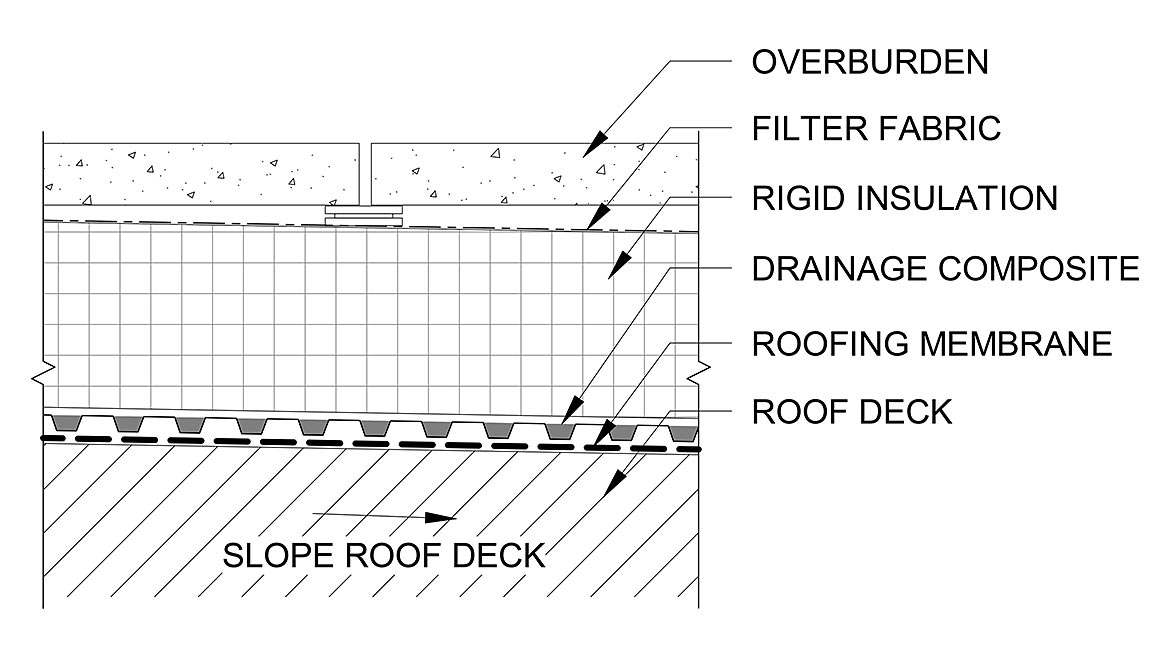 Figure 2.a – Example protected membrane roof (PMR) assembly.
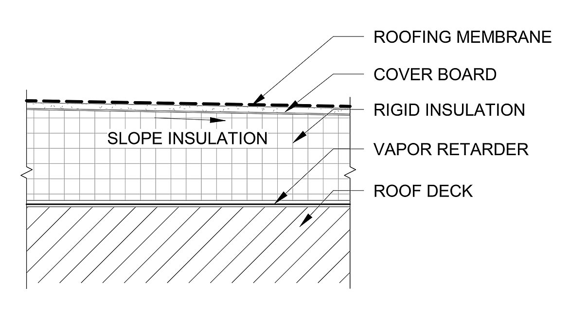 Figure 2.b – Example conventional exposed membrane roof assembly.
Curtainwall Construction Method
Aluminum-framed curtainwalls may be designed and constructed generally as either a stick-built system (Figure 3.a) or a unitized system (Figure 3.b). The Whole Building Design Guide defines a stick-built curtainwall as a system where “curtainwall frame (mullions) and glass or opaque panels are installed and connected together piece by piece.” A unitized system is defined as where “the curtainwall is composed of large units that are assembled and glazed in the factory, shipped to the site and erected on the building” [2]. Often in a stick-built system, the framing elements are rectangular aluminum extrusions, whereas in a unitized system, the framing is split into two half-mullions with interlocking components. The horizontal interlocking components consist of a stack head, which has a continuous upturned leg (i.e., “chicken-head”), and a stack sill, which includes a continuous slot sized to receive the chicken head.
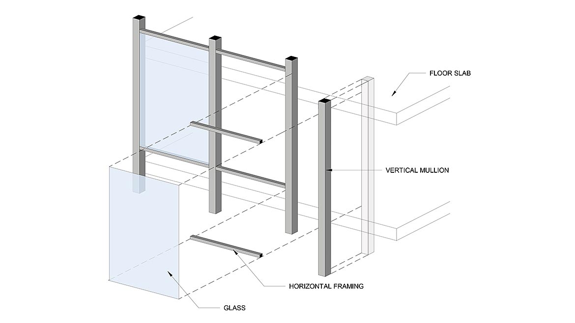 Figure 3.a – Stick-built curtain wall sequence.
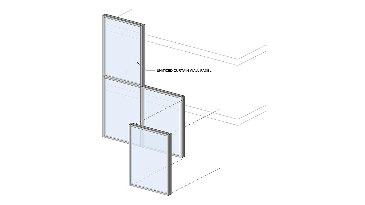 Figure 3.b – Unitized curtain wall sequence.
Curtainwall Structural Support and Accommodation for Movement
A curtainwall system must transfer both the gravity loads (e.g., self-weight) and the lateral loads (e.g., wind loads) back to the building superstructure, typically via anchorage at building floor slabs. Curtainwall systems must be designed and anchored to the building to accommodate in-service building movements. This includes vertical floor slab deflections due to live loads and creep, horizontal inter-story drift due to wind and seismic loads, and thermal movements of the curtainwall.
There are several types of curtainwall anchor configurations, ranging from “F” and “T” clips for curtainwalls spanning slab to slab, or “J” hooks or angles at intermediate floors where the curtainwall is supported outboard of the slab edge. In a unitized curtainwall system, units are typically gravity-supported on each floor slab and lateral loads are transferred between units by the interlocking profile engagement at the stack joint at floor levels. In some instances, unitized curtainwall units may be gravity-loaded onto the unit below using dead-load shim stacks between interlocking mullions. A stick-built system outboard of the slab edge typically anchors the vertical mullion to the floor slab with angles or a U-shaped bracket, while lateral loads are resisted internal sleeves within the vertical mullions at splice joints.
For the top of curtainwalls in parapet applications, the structural support and attachment must be designed to accommodate the absence of a floor slab at the top of the curtainwall parapet. Gravity loads can be supported either on the curtainwall unit below or top-hung from an independent outrigger structure on the adjacent roof surface. Lateral load transfer can be achieved either with a similar independent outrigger structure (Figure 4.a) or internal structural reinforcing embedded within the vertical mullions designed to cantilever from the gravity support condition at the roof slab (Figure 4.b).
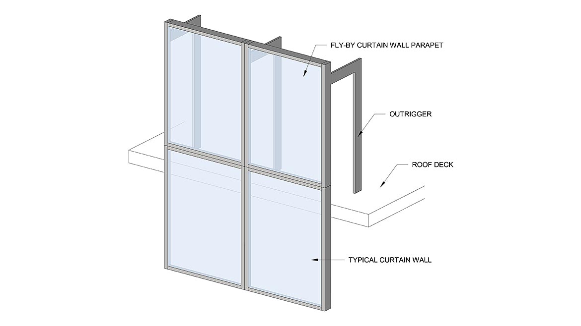 Figure 4.a – Stick-built curtain wall sequence.
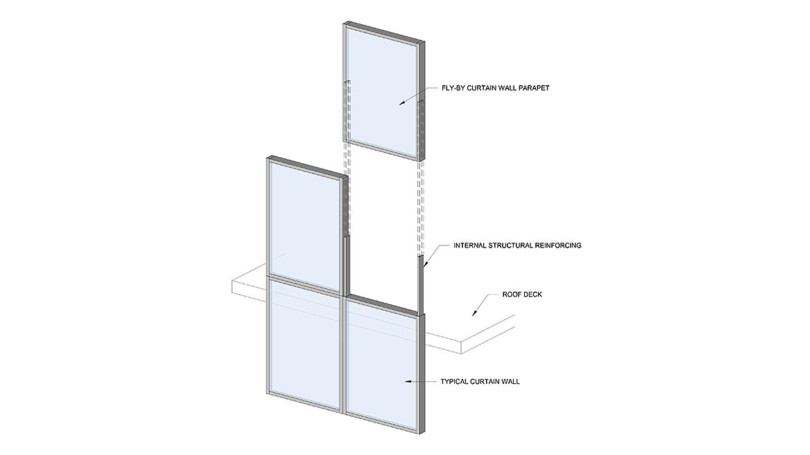 Figure 4.b – Fly-by curtain wall parapet unit top-hung from outrigger
Fly-By Parapet Design Options
Generally, the outer portion of curtainwall assemblies (the “wet zone”) are weather tight and include water management features (e.g., glazing pocket and weeps) to direct and evacuate any water bypassing the outer rainscreen seals. The interior facing sides of curtainwalls are, “not designed to be watertight, nor do they include the water management and drainage provisions that are present at the exterior side of the system” [3]. Detailing of opaque curtainwall parapets is therefore often guided by a general overarching principle: extend the roofing assembly over the curtainwall so that the interior facing side of the mullion is inside the building. Contrast to a fly-by curtainwall parapet, where the interior-facing elements are now exposed to the exterior, and one can see why the detail increases in complexity and challenge.
Compared to stick-built systems, unitized curtainwall stack joints offer a convenient concealed vertical termination point for the roofing assembly flashing and greatly improve the durability and reliability of the roof-to-curtainwall transition. Integrating roofing with a stick-built system requires more intricate detailing provisions, as discussed in the sections below.
There are numerous approaches to detail a fly-by parapet depending on the project-specific parameters that acknowledge the design considerations discussed above, ranging from off-the-shelf products to customized solutions. The sections below offer conceptual examples and basic principles for integrating a protected membrane roof assembly with commodity systems for both unitized and stick-built curtainwalls, based on the author’s experience with these systems in their practice.
Concept 1—Unitized Curtainwall with Outrigger Support System
This concept incorporates a unitized curtainwall system and an independent outrigger support system, featuring similar conceptual detailing to the traditional opaque curtainwall parapet shown in Figure 1. The outrigger may either resist gravity and lateral loads (i.e., top hung from outrigger) or lateral loads only (i.e., dead loaded on unit below). This approach generally consists of the following basic features, which are also illustrated in Figure 5:
- Curtainwall unit stack joint at least 8 inches above the overburden surface to limit exposure to water from buildup of snow or ice (as recommended by the National Roofing Contractors Association [4]).
- Slab edge fire safing and curtainwall spandrel assembly (e.g., shadowbox or insulated back pan) to conceal the slab edge.
- Continuous curb around the roof edge covered by the roofing membrane base flashing, sloped towards the roof. The curb elevation should be set above the roof overburden but below the curtainwall stack joint to elevate the vulnerable roofing membrane termination.
- Membrane flashing bridging between the curtainwall and roofing membrane on the curb to complete the building’s air and water barrier. Note the membrane flashing requires continuous support, which can be achieved with sheet metal spanning across the gap between the two systems. The membrane flashing terminates on the back of the chicken head to provide a protected and concealed membrane termination on the vertical surface. If differential movement between the curtainwall and roof slab is anticipated (e.g., a lateral-only connection at the roof slab), the membrane flashing and its support must accommodate movement.
- Metal counterflashing covering the membrane flashing on the backside of the curtainwall unit to protect from ultraviolet exposure and mechanical damage.
- Elastomeric membrane (e.g., silicone sheet) covering splice joints in the chicken head and horizontal mullion to maintain the weather-tightness of the chicken head. This fly-by parapet configuration allows the roofing system flashings to integrate directly with the curtainwall stack joint head at the roof line. This effectively provides a through-wall flashing system that separates the upper portion of the fly-by parapet from the building envelope and eliminates the need for the backside (i.e., normally interior side) of the curtainwall above to be weather tight. Although the steel outriggers may be aesthetically undesirable, depending on roof occupancy and use, they avoid internal reinforcing and allow for an uninterrupted plane for the membrane flashing. Because of this, Concept 1 generally offers greater reliability from the standpoint of long-term weather protection compared to Concepts 2 through 4, described below.
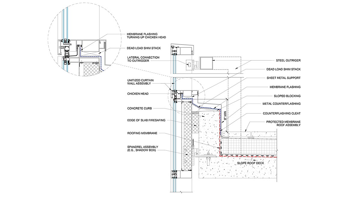 Figure 5 — Concept 1: Unitized curtain wall with outrigger support system.
Image courtesy of Simpson Gumpertz & Heger, Inc. and Oldcastle BuildingEnvelope.
Concept 2—Stick-Built Curtainwall with Outrigger Support System
Outrigger support systems can similarly be used for stick-built curtainwalls and incorporate similar basic principles as Concept 1 above (e.g., location of splices, spandrels, curbs, and rigid sheet metal). The primary distinction between the two is that stick-built curtainwall systems do not have split horizontal mullions, into which the membrane flashing can be integrated and sealed. Instead, the membrane flashing must adhere directly onto the curtainwall frame on the interior-facing side of the curtainwall, where it is vulnerable to water intrusion. This inherently makes a stick-built fly-by curtainwall parapet less reliable compared to the unitized system since the membrane flashing termination is unable to directly integrate with the established water management features of the curtainwall.
To avoid this inherent disadvantage, the stick-built curtainwall parapet can be separated from the primary building envelope by using the outrigger to independently support the parapet from the remainder of the curtainwall. In this configuration, the roof flashings extend between two parallel horizontal mullions adjacent to the roof curb (Figure 6), mimicking the functionality of the split mullion for a unitized curtainwall system.
Since a stick-built curtainwall system typically relies on internal reinforcing at splices to provide lateral restraint, the outrigger system must provide two anchor points at each vertical mullion, one for gravity support and the other for lateral support. Completely separating the parapet from the lower curtainwall avoids internal reinforcing penetrating through the membrane flashing. Unlike a unitized system, the stick-built system does not feature a chicken head where the membrane flashing may turn up against. Since vertical membrane terminations are less susceptible than horizontal membrane terminations, the membrane flashing should extend down into the curtainwall glazing pocket, where it can be compressed, as illustrated in Figure 6.
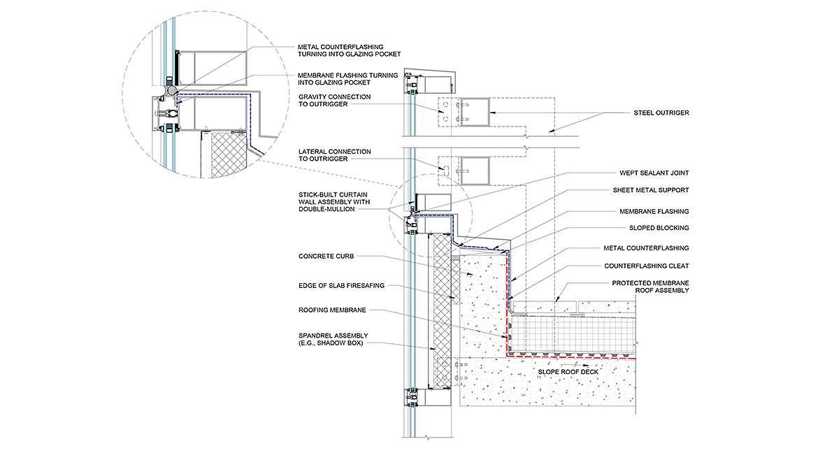 Figure 6 — Concept 2: Stick-Built Curtain Wall with Outrigger Support System.
Image courtesy of Simpson Gumpertz & Heger, Inc. and Oldcastle BuildingEnvelope.
Concept 3—Unitized Curtainwall with Cantilever Support System
Although more reliable, outrigger support systems may not be possible under all circumstances. Concept 3 therefore shows an approach using steel reinforcing posts embedded in the vertical mullions to resist lateral loads, instead of the independent outriggers. While this option avoids the visual impacts of exposed framing, the steel posts interrupt the plane of membrane flashing within the stack joint and require detailing of the membrane flashing to maintain water barrier continuity. At the steel reinforcing, the membrane flashing must turn up and seal around the steel reinforcing posts on all sides (Figure 7). Further, the steel reinforcing post must be welded air- and water-tight (including a welded cap at the top), since it must function as an extension of the building envelope. Detailing the steel posts is workmanship-dependent, but if executed well, this detailing approach can be successful. Because this option relies on cantilevered internal reinforcing, this option may be limited to a guardrail height top unit (e.g., story-tall unit may be structurally infeasible).
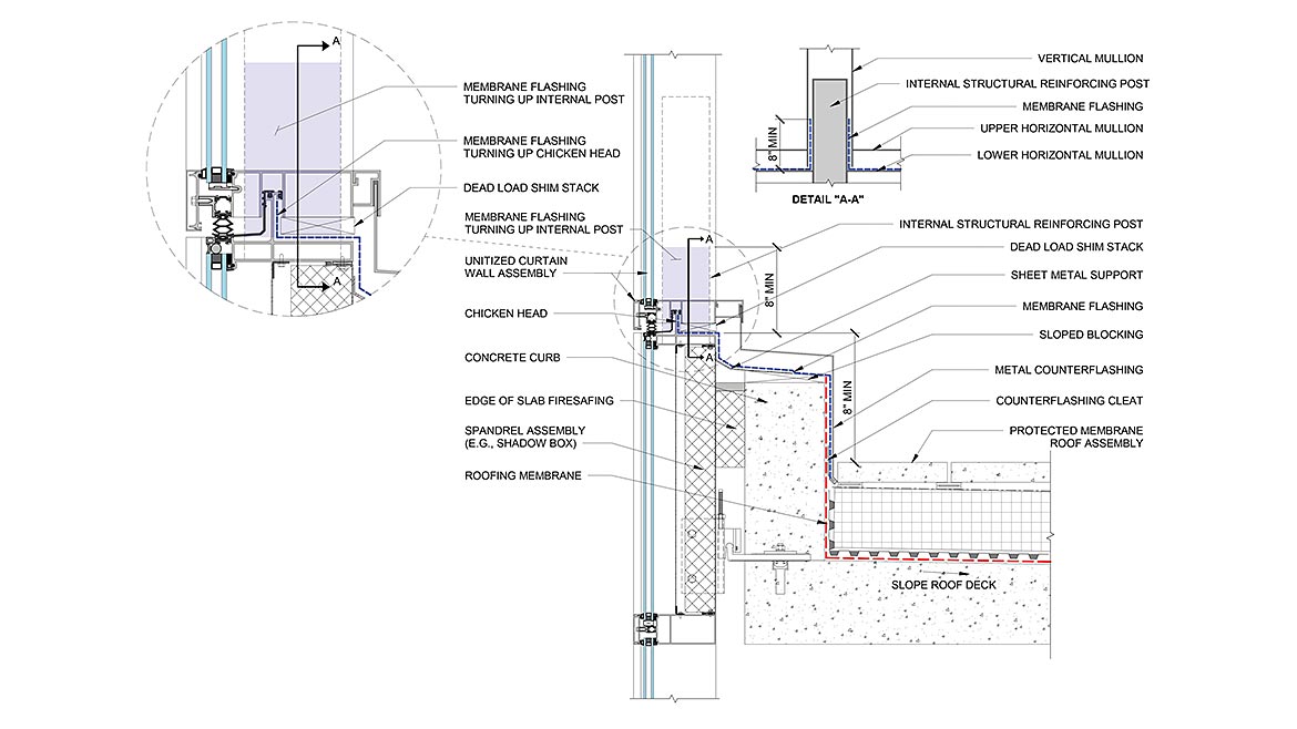 Figure 7 — Concept 3: Unitized Curtain Wall with Cantilever Support System.
 Image courtesy of Simpson Gumpertz & Heger, Inc. and Oldcastle BuildingEnvelope.
Concept 4—Stick-Built Curtainwall with Cantilever Support System
Without either the split horizontal mullion inherent to unitized curtainwall or the outriggers suspending a completely separated stick-built curtainwall unit above the roof line, the options for reliable detailing become limited. A first instinct may be to turn the roofing membrane up the interior side of the glass and mullions; however, skyward-facing termination and seals which are not protected will degrade over time and will ultimately cause leakage into the building. Instead, combine the membrane and metal flashing turning into the glazing pocket shown in Concept 2, with membrane turning up the steel reinforcing post shown in Concept 3, as an alternative to sealing directly to the glass (Figure 8). Any connections to the internal reinforcing post which are exposed to the exterior must be detailed water tight, since the reinforcing post becomes an extension of the building’s air and water barrier. The stick-built curtainwall with internal reinforcing posts is the most workmanship-dependent of the four concepts and is subject to the limitations of the manufacturer; review the feasibility of this approach with the selected manufacturer early in the project.
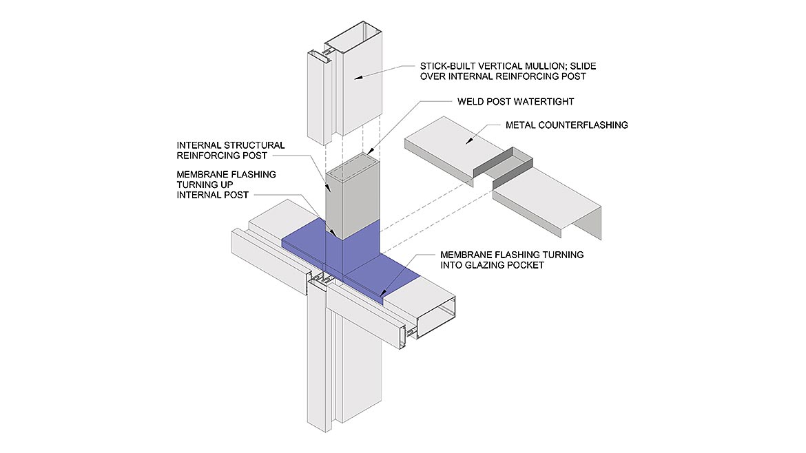 Figure 8 — Concept 4: Stick-built curtain wall system with cantilever support system.
Summary and Detailing Tips & Tricks
This article addresses some, but not all, possible design strategies to integrate a fly-by curtainwall parapet with the roofing systems. Each project’s design intent and constraints create unique challenges to overcome. Many curtainwall manufacturers have developed proprietary approaches for constructing a fly-by curtainwall parapet. Designers must evaluate whether the selected manufacturer’s standard details and “kit-of-parts” can fulfill the design intent and long-term performance expectations or if the project necessitates a custom solution. Commodity products, which are inherently less customizable than custom products, have inherent limitations from the standpoint of detailing, maintenance, and risk of air and water leakage in service.
Keep in mind the following detailing principles, tips and tricks next time you encounter a fly-by curtainwall parapet:
- Unitized curtainwall offers inherent features that simplify integration with roofing base flashings.
- Good design is important, but results come down to execution; incorporate a fly-by parapet mockup and performance testing to the project specifications.
- Work with the curtainwall and roofing manufacturers early in the project to avoid changes during construction.
- Check compatibility between membrane flashings and roofing.
- Consider and incorporate differential movement into the design.
- Where possible, terminate membrane flashings either on an upturn or a downturn (i.e., not on a horizontal).
- Raise roofing transitions onto curbs out of the plane of water travel.
- Avoid fasteners between “wet-zones” and “dry-zones.”
- Protect skyward-facing sealant joints or membrane flashings to the extent practical.
- Always support membrane flashing using a smooth rigid substrate.
- Slope flashings back towards the roof.
Regardless of which individual systems are selected for the fly-by curtainwall parapet, it is how they come together which determines the reliability of the final detail. Early conversations with all parties on the design and construction teams provides the best opportunity for successful in-service performance of the fly-by curtainwall parapet.
References
Cited References
1. Occupational Safety & Health Administration [OSHA]. (1995, January 26). Safety and Health Regulations for Construction – Fall protection systems criteria and practices. (Standard No. 1926.502). Retrieved from OSHA.gov: https://www.osha.gov/laws-regs/regulations/standardnumber/1926/1926.502.
2. Vigener, N., & Brown, M. A. (2016, May 10). Building Encelope Design Guide - Fenestration Systems - Curtain Wall. Retrieved from Whole Building Design Guide: https://www.wbdg.org/guides-specifications/building-envelope-design-guide/fenestration-systems/curtain-walls
3. Kivela, Joshua B. & McCowan, Derek B. (January 2014). Creative Solutions for Challenging Curtain Wall Conditions. IIBEC Interface. pp. 22-28. Available at: https://iibec.org/wp-content/uploads/2014-01-kivela-mccowan.pdf
4. Bollnow, Tom. (January 2000). Base Flashing Height Requirements. Professional Roofing / National Roofing Contractors Association. P. 61. Available at: https://www.nrca.net/technical/librarydetail/g7p1XtQbUGQ=
General References
Murray, Scott C. (October 2009). Contemporary Curtain Wall Architecture. Princeton Architectural Press.
This article was originally published in Building Enclusure magazine.
Looking for a reprint of this article?
From high-res PDFs to custom plaques, order your copy today!


