All things gypsum: Gypsum Board Sound Control Systems
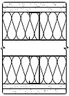
Illustration 1: Double row of steel studs with double layer of 5/8-inch gypsum board on outside surfaces and insulation in stud cavities.
One of gypsum board's many qualities that make it the most popular material for partitioning interior spaces is its inherent sound attenuating properties. Gypsum board contains sufficient mass to inhibit most low frequency sound waves and has sufficient resiliency to inhibit sound waves at the higher frequencies. In other words, gypsum board reduces the sound passing through it at both ends of the frequency spectrum.
Gypsum board is produced in a variety of thicknesses and each thickness is effective at blocking a different range of frequencies. So, for optimum sound blocking, several layers of gypsum board, each a different thickness, is ideal. This concept is simple enough but putting it to good use requires using one of several sound-reducing approaches.
Sound Transmission Classes
If you've been reading this column for the last several months, you are aware that the Gypsum Association has recently published the 18th edition of its Fire Resistance Design Manual. Previously, we've discussed some of the new fire-resistive designs that appear in the manual but until now, we haven't focused on one of the other main features of the manual-the sound control information. Many of the listings in the manual not only show the fire-resistance rating of a design but also its sound control properties. In most cases, this appears as a sound transmission class rating.An STC rating is a number that represents an average of a system's sound dampening properties. Occasionally, you will also see a field sound transmission class rating, which, as the name suggests, is the sound transmission class rating for a building assembly that has been determined in the field or under conditions differing slightly from those in the lab. The higher the STC or FSTC rating, the more sound that is prevented from passing through to the adjoining areas.
The ratings for these sound transmission classes are determined by tests conducted according to procedures set forth in either ASTM E 90, "Standard Test Method for Laboratory Measurement of Airborne Sound Transmission Loss of Building Partitions," which is the procedure for measuring the sound transmission loss in a laboratory, or ASTM E 336, "Standard Test Method for Measurement of Airborne Sound Insulation in Buildings," which is the procedure for measuring sound transmission loss in the field.
Blocking Overhead Noise
STC and FSTC ratings apply to walls, partitions and various ceiling assemblies, which are the main players in preventing sounds, such as loud conversation or music from traveling room-to-room. However, the sound of foot traffic also travels through floor-ceiling assemblies. The measurement for this variety of sound transfer is the Impact Insulation Classification, which is determined by the procedures set forth in ASTM E 492, "Standard Test Method for Laboratory Measurement of Impact Sound Transmission Through Floor-Ceiling Assemblies Using the Tapping Machine." The higher the IIC, the lower the amount of sound that is transferred into the area below.Section IV of GA-600 is an index to the systems listed in the manual by STC rating. The designs in this index are grouped by their assembly type (e.g. non-combustible walls and partitions, wood-framed walls and partitions, shaft walls and area separation walls) and STC range. The higher STC numbers show the most sound-dampening designs.
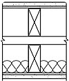
Illustration 2: Double row of wood studs with a base layer of 1/4-inch gypsum board and a top layer of 1/2-inch gypsum board on each outside surface and insulation in one stud cavity.
Sound Rated Designs
One of the higher rated designs (55 to 59 STC) that appears in the new edition of GA-600 bears GA file number WP 1516. This generic design uses several sound-deadening devices, which include a double row of steel studs, glass fiber insulation in the stud cavities, and two layers of 5/8-inch thick gypsum board that are screw-attached to the steel studs. The joints in the different layers of wallboard are staggered by 24 inches, which impedes the passage of sound.The use of the double stud wall creates a dead air space that prevents direct sound transmission between the two wall surfaces. The insulation in the stud cavities of each row of studs also helps absorb some of the sound and the double layer of 5/8-inch wallboard on each side of the wall presents a large mass that dissipates much of the sound. (See Illustration 1.)
Another generic design with a similar sound rating bears GA file number WP 5510. This design uses a double row of wood studs, a base layer of 1/4-inch gypsum wallboard on the exposed side of each row of studs, a face layer of 1/2-inch gypsum wallboard that is applied over the base layer and 11⁄2 inches of mineral fiber insulation between the studs. This design uses the air gap between the two rows of studs to trap unwanted sound and two layers of gypsum board that are different thicknesses to reduce two different bandwidths of sound that pass through the assembly. The mineral fiber insulation also helps to absorb the reflection of the sound that enters the air gap between the rows of studs. (See Illustration 2.)
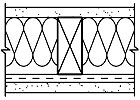
Illustration 3: Single row of wood studs with resilient channels on one side with a layer of 5/8-inch gypsum board on each surface and insulation in the stud cavity.
Glass fiber or mineral fiber insulation further dampens the sound in the wall cavities. And finally, an additional layer of 5/8-inch wallboard is screw-attached to the other side of the studs, which creates the last barrier to the sound passing into the adjoining area. This design carries a 50 to 54 STC rating. (See Illustration 3.)
The generic floor-ceiling system depicted in GA file FC4370 offers both an STC rating of 45 to 49 and an IIC rating of 39. To achieve this level of sound reduction between floor levels, resilient channels are screw-attached at right angles to steel floor joists at 16-inch intervals. Two layers of 1/2-inch gypsum board are then screw-attached to the resilient channels. The joints of the two gypsum board layers are staggered to prevent the passage of sound. Glass fiber insulation placed between the joists reduces noise in the joist cavities. (See Illustration 4.)
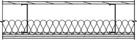
Illustration 4: Steel joists with resilient channels supporting two layers of 1/2-inch gypsum board with insulation in the joist cavity.
For additional information on this topic, Section III in GA-600 offers a brief but thorough discussion of these principles and techniques.
This is just a small sampling of the designs available for reducing the transmission of sound from one area to the next. Each of these designs employs several techniques for reducing unwanted sound and if followed carefully, will provide a much quieter environment. As with a fire-rated system, quality construction techniques must be incorporated for a sound control system to function as tested and the prescribed materials must be incorporated into the constructed system.
Looking for a reprint of this article?
From high-res PDFs to custom plaques, order your copy today!


