Supercharged EIFS
A dissection into the seemingly unknown PE EIFS system.

In 1953, the Studebaker Commander Starlight Coupe, was considered an American landmark for styling and considering its sporty design, was very affordable. It was thought to have a strong appreciation potential due to its high performance. With a 232-cubic-inch, overhead valve V-8, it kicked out an impressive 120 HP and got 20 mpg on regular gas. It won the Motor Trend’s award for “the most aesthetically styled” and later was considered a “milestone” by the Museum of Modern Art.
The beauty (pictured) is one of those original Studebakers, except this one has a supercharged V-8 that kicks out an impressive 700 horsepower.
In 1969, a brick salesman brought a high performance exterior cladding to America. It was lightweight, easy and quick to apply, and out-performed exterior wall assemblies for insulation value. During the energy crunch of the ’70s, it proved to be an inexpensive means of reducing energy usage in buildings. The finish was color-fast and available in many types of textures. Dryvit barrier EIFS was very popular and soon became the exterior cladding of choice.
Back in the Day
During the heyday of EIFS, other higher-performance systems were developed. One was the addition of a secondary water-resistive barrier, a plane between the WRB and the foam, and the first drainage EIFS was invented. Then to really go the extra mile, an even higher performance, pressure equalized EIFS was developed. And, it is the pressure equalized EIF system that became the Supercharged Studebaker of exterior insulation and finish systems.
This month, I want to talk about how a pressure equalized EIF system (PE EIFS) works. And for those of you who have never heard of PE EIFS, or even thought it was a myth, take a load off and contemplate in the wonders of what I call Supercharged EIFS.
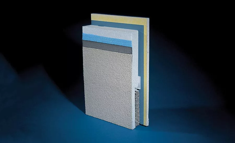
Barrier EIFS is so named because the basecoat, mesh and finish create a barrier, outside of the EPS foam, that keep weather out of the clad structure. Drainage EIFS is barrier EIFS, with the suspenders of an additional WRB, a drainage plane and weeping mechanism. PE EIFS is all of this and an engineered design that prohibits wind-driven moisture from entering the wall cavity. It is a design, within a defined section of EIFS cladding, to instantaneously equalize the pressure in the EIFS cavity. Let’s begin the dissection.
In barrier EIFS, the foam is flat and adhered directly to the substrate with no particular orientation of the adhesive. It may or may not have a secondary WRB applied to the substrate. In drainage EIFS, a secondary WRB is always used and the adhesive is applied to flat boards in a vertical orientation to provide a path for drainage. Other drainage systems may use foam boards that are grooved on the backside in a vertical configuration. Still, other EIFS drainage systems use a defined drainage medium between the WRB and a flat foam.
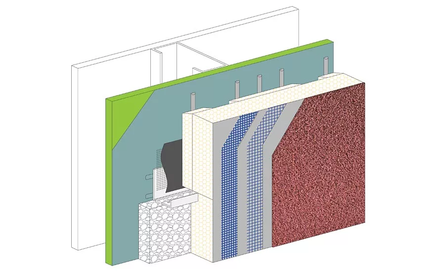
In PE EIFS, the WRB is usually an air and moisture barrier product. The foam is grooved vertically and horizontally, and is adhered to the WRB. The grooves in the foam align with each other to create engineered passageways, of which are contained within a defined cavity area. The perimeter of this defined cavity section is solid foam, containing the area of pressure equalization. At the bottom of each cavity is a “vent” to allow for pressure equalization and also for incidental moisture drainage.
Science
It was taught back in science class, high pressure always moves to areas of low pressure; nature always seeks to equalize pressure. In our modern buildings, higher air pressures on the exterior—like storms and winds—can infiltrate into our interior environment via the smallest of entry points. Nature being the insistent being it is, can force itself into the lower pressure environment of our cozy interiors bringing everything it contains with it. We refer to this often as moisture and air infiltration.
PE EIFS deals with this in a scientific way by creating a cavity where air pressure cannot build up, a cavity where equalization can occur. The outside pressure is instantaneously equalized within the cavity/drainage plane of the EIF system, the space between the foam and the WRB. The equalization eliminates the potential of wind driven rain pushing moisture into your wall cavity.
I recall an event told to me by an engineer who was involved in the testing of the first PE EIF systems: Two engineers walked into a bar, the third one ducked. OK, that’s not the story, this one is: A group of engineers wished to test the efficacy of a pressure equalized cavity within an EIF system. During the application of the EPS foam, they strategically placed pressure meters within the EIFS cavity at varying locations. They then placed more sensors on the outside of the system in close proximity to the interior ones.
Additional sensors were placed inside the wall cavity again in close proximity to the locations of the other sensors. Each group of sensors was assigned a color to be illustrated on a graph; green for the interior of the wall, red for the EIFS cavity, and black for the exterior. The wall cavity was secluded from the exterior cladding as it would be in any building structure.
The idea was to vary the pressure on the EIF system side, and compare the three color’s movement on the graph. On the first test they had a steady, level green line, representing the inside or wall cavity location, and one black line that went up or down representative of the pressure fluctuations. That was it, only two lines, not three.
The group thought the sensors within the EIF system were malfunctioning and tore apart the whole assembly and rebuilt it with new sensors. Same test, same results, two lines, one steady green, the other black, showing the pressure fluctuations. The group was done for the day and decided to give it another go and re-build and re-test the next day.
The story goes that that very evening, over a nice dinner and a couple of beers, the proverbial light went off and they realized that the reason for only two graph lines being illustrated, was that the two groups of sensors, red and black, were reading true and following the pressure fluctuations of the test procedure. The cavity in the EIF system in fact, was instantaneously equalizing with the exterior, thus both sensor groups were reading identical and showing up as a single black graph line.
To say the least, they were quite pleased at the performance of the PE EIFS.
When I was first introduced to the PE system my feeble mind assumed that wind would be blowing behind the EIFS and with it would come dust and moisture. I further questioned how EPS could insulate effectively if cold air was introduced to a cavity within the EIF system. I challenged one of the aforementioned engineers, and was quickly schooled on the facts. First, in order for a “wind” to blow behind something there would need to be an inlet and exhaust location and the space would need to allow air to flow freely. Airflow, like water flow, will always follow the path of least resistance, and the very small space between the foam and WRB are far more restrictive than the great outdoors, the space outside of the EIF system.
As for the temperature variation supposition I had, like air and water, temperature changes are caused by the movement from warm to cold. Since there is no wind or water movement in the EIFS cavity, there is no more temperature loss than that which is normal for any EIFS clad wall assembly. Furthermore, since the pressure was instantaneously equalized, no air or water flow could ever exist within the EIFS cavity. School’s out.
As an affordable exterior cladding, EIFS stands alone, a veritable engineering superstar, insulating and protecting our structures. When an EIF system is supercharged, like a PE system, it easily wins over other claddings in performance. Like our Studebaker, a seemingly normal exterior with a pleasing finished appearance, can hide a supercharged performance capability. Sometimes, one can be surprised when they “check under the hood” and see the performance powerhouse an engineered system, and car, can be hiding.
Looking for a reprint of this article?
From high-res PDFs to custom plaques, order your copy today!


