How to Utilize Ceilings for Efficiency
Rethinking data center containment enclosures and ceilings to maximize efficiency.
Most legacy computer rooms and data centers are equipped with raised floors to accommodate data and power cables and to distribute cold air supply to the IT equipment. As data centers become larger, on-slab designs that use Hot Aisle Containment become a more popular choice. The reasons are numerous and include: reduced ducting, flexible airflow management, IT equipment weight supported directly on slab, cost avoidance of raised flooring, reduced maintenance cost, and more robust seismic performance on slab versus raised floor. Good containment systems, which include aisle containment enclosures and overhead ceilings, become critical.
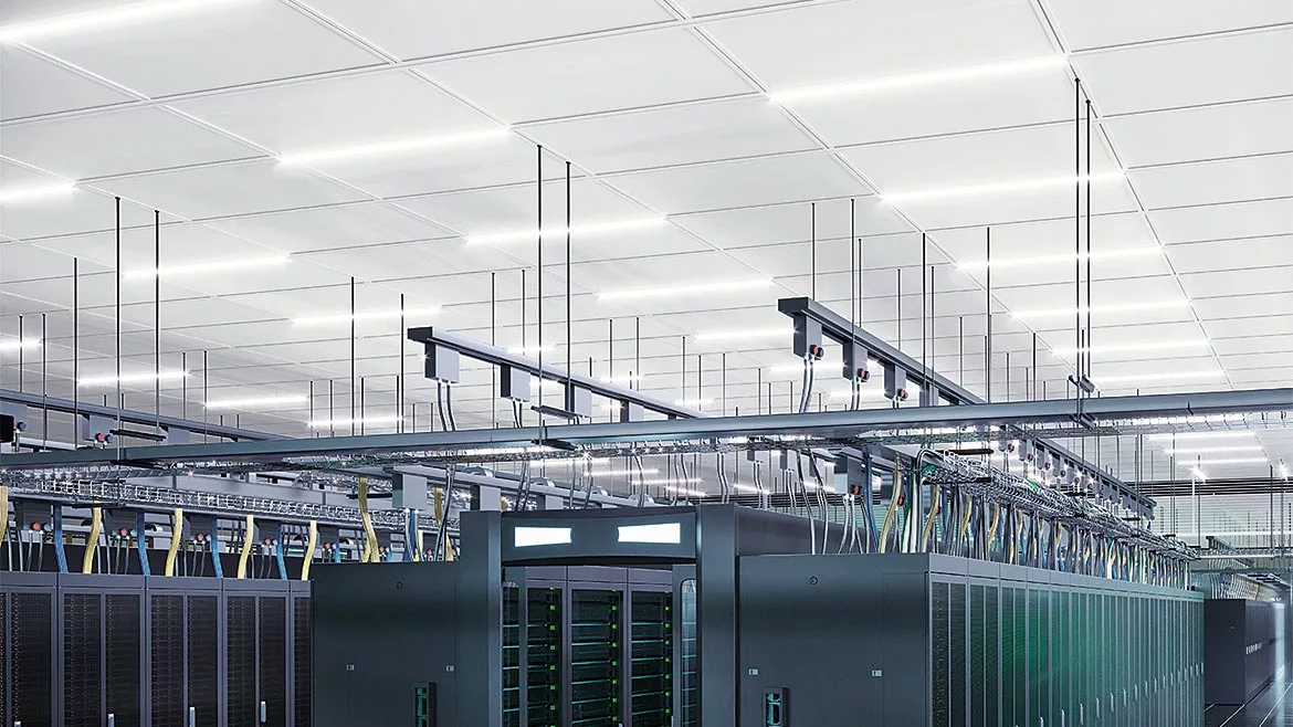
Figure 1: Hot Aisle Containment enclosures with gasketed, low leakage rate structural ceiling system. Ceiling panels form a low-leakage return air plenum for the hot aisle. Suspension grid supports infrastructure and eliminates leak-causing rod penetrations through the ceiling.
Enclosures and Ceilings Affect Containment
In a typical air-cooled data center, airflow management is about delivering cool air to the IT equipment and returning warm air to the computer room air hander. Cooling is most efficient when hot and cold airstreams are separated to prevent mixing thereby improving predictability and control. The containment of hot and cold air is one of the most promising energy-efficiency measures available to both new and legacy data centers.
Hot aisle containment is a popular strategy where cold air is supplied to the room and passed through the IT equipment before returning to the CRAH. Ideally, the air supplied by the CRAH is in balance with the air demanded by the IT equipment so that conditioned air passes once through the racks. In the real world, some amount of air bypasses the IT equipment or recirculates through it due to leakage in containment structures. The result is elevated fan power and reduced chiller efficiency.
Containment options are numerous. Recently introduced choices include well-designed enclosures, combined with low-leakage gasketed ceilings and structural suspension systems. The suspension system is also the infrastructure carrier for busway, cable tray, and fiber. By coordinating the choice of enclosure, ceiling, and suspension, significant leakage paths can be reduced and controlled.
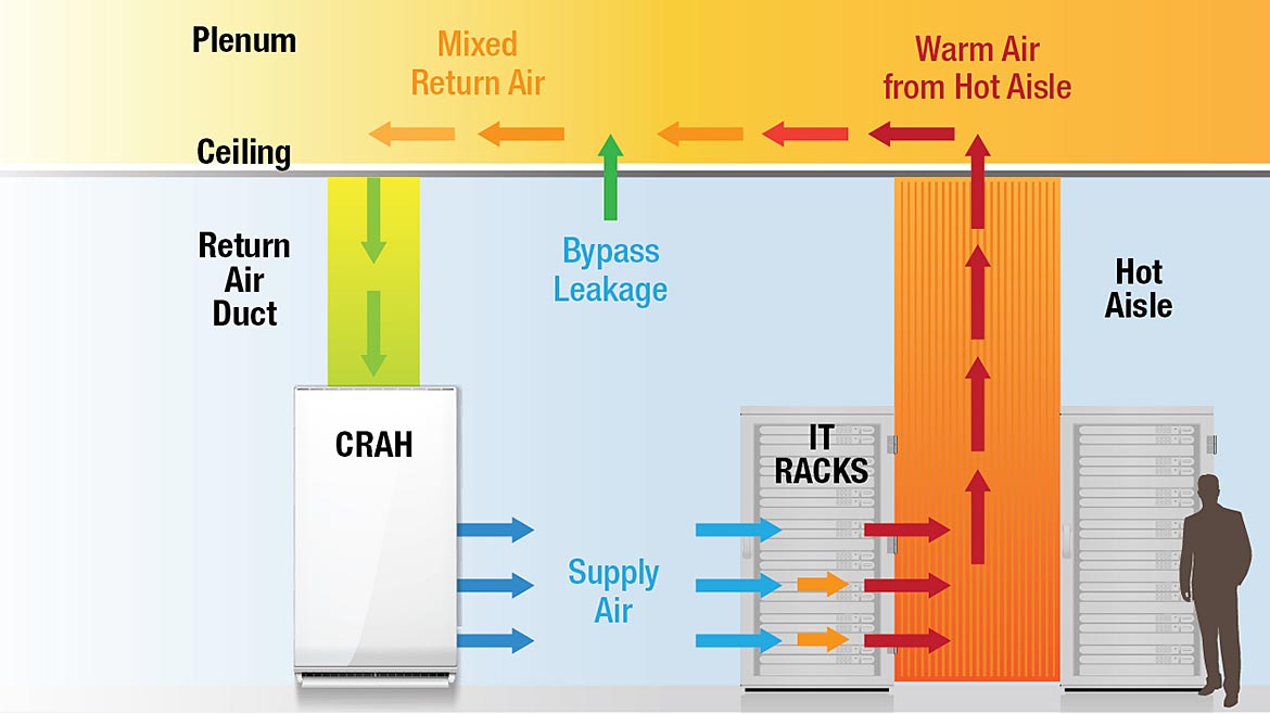
Figure 2: Cool supply air passes through the IT racks, picking up heat, and enters the hot aisle to leave through the ceiling plenum. Some cool air can also bypass the server and leak through the ceiling into the plenum. Careful selection and matching of enclosures and ceiling systems can greatly reduce wasteful by-pass leakage.
Ceiling Plenums are Part of the Containment System
Designers must pay attention to components that are known sources of fugitive and distributed leaks to reduce bypass losses. In the case of HAC systems, ceilings form a return air plenum and, more importantly, separate the warm return air from the cool conditioned room. They become an important part of the overall air containment strategy. Gaps around the tiles and drop rod penetrations allow conditioned air to bypass the IT equipment. The bypassed air must be made up by increasing cold air supply from the cooling units, thereby consuming more energy.
Typical ceiling systems have leakage rates far larger than raised floor systems. At a differential pressure of 0.02 [in WC], a raised floor system may leak about 0.05 to 0.30 [cfm/ft2]. A non-gasketed ceiling with typical drop rod penetrations will leak about 1.44 [cfm/ft2]. When factory-gasketed ceiling tile is combined with an aluminum structural grid, leakage is reduced to about 0.19 [cfm/ft2] and becomes comparable to raised floor and containment wall systems.
The use of factory-gasketed ceiling tiles in conjunction with an aluminum structural grid is an engineered solution designed for data centers. The tiles feature a perimeter gasket that reduces ceiling leakage at the tile edges. The structural grid supports the tiles and also eliminates drop rod ceiling penetrations. Paired together, the system reduces bypass leakage down to levels matching the rest of the containment system. This type of ceiling solution delivers accessibility and containment that improves both cooling efficiency and saves fan energy.
To illustrate this, heat balance and airflow calculations were solved to satisfy the governing equations for 4,000 random combinations of design and operating parameters. The resulting chart clearly shows the effect of changing from a typical (high leakage) ceiling to the (low leakage) gasketed ceiling with a structural grid system.
In these simulations, typical “leaky” ceiling systems may have bypass leakage values ranging from 0.6 to 2.0 percent. Improved ceiling and grid systems reduce this leakage to below 0.6 percent. Reduced leakage across this containment plane reduces bypass losses, thereby reducing fan energy and operating costs.
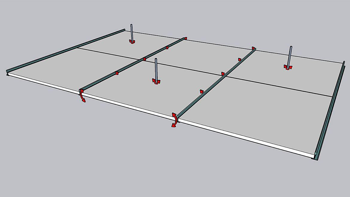
Figure 3: Typical non-gasketed ceiling tile with tee-bar grid and drop rod penetrations. Leakage rate may be 1.44 [cfm/ft2] at 0.02 [in WC]. Uncontrolled leak points contribute to bypass leakage.
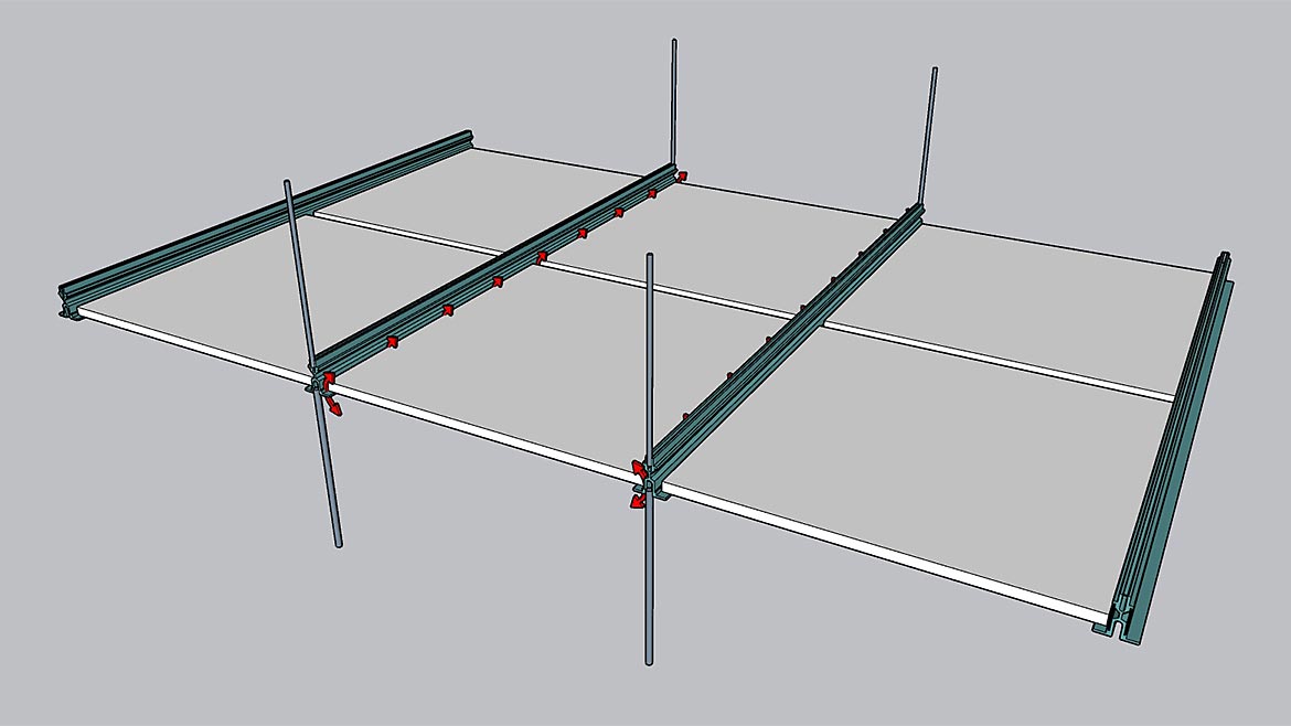
Figure 4: Newly developed gasketed tile systems with structural suspension grid reduces leakage at the tile perimeter and eliminate leakage around drop rods. Leakage rate may be 0.19 [cfm/ft2] at 0.02 [in WC]. The ceiling system, and resulting return air plenum space, become a low-leakage part of the overall containment system.
Maximize Energy Efficiency and Sustainability
Ideally, total cooling capacity (supply airflow) would exactly match the IT load (demand airflow) and cooling unit set points would be raised as high as practical. However, there are fugitive leaks within the IT racks. The goal is to minimize this leakage as much as possible through good containment enclosures and ceilings. When this is achieved, there will be consistent supply temperatures across the server inlets on all racks throughout the data center. This level of airflow management may allow cooling set points to be increased resulting in additional energy savings, higher equipment reliability and lower Mean Time Between Failures.
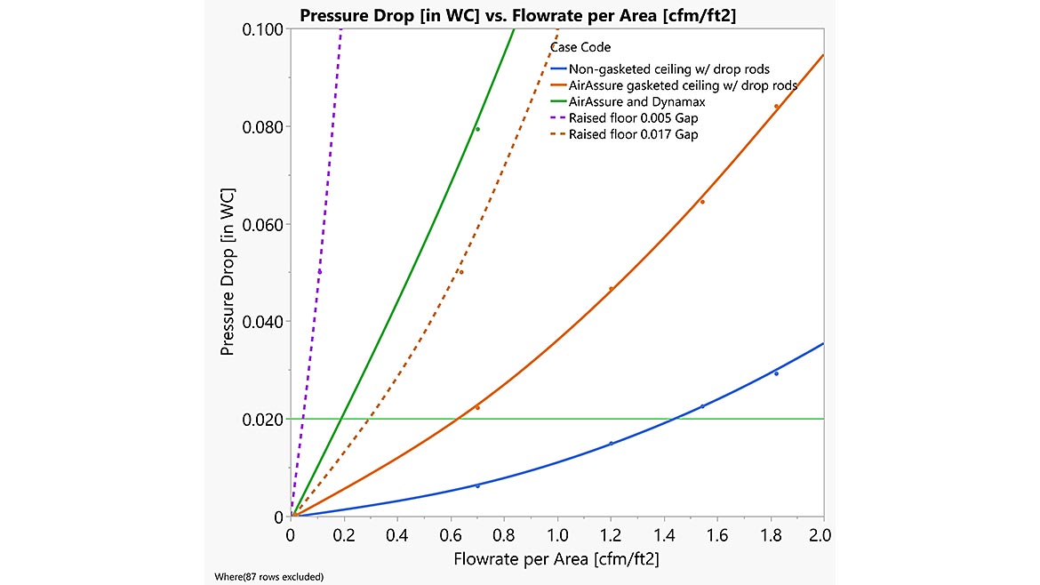
Figure 5: Leakage resistance curves for a wide range of ceiling and suspension systems. Recently developed ceiling systems can reduce leakage rates to the level of raised-floor systems.
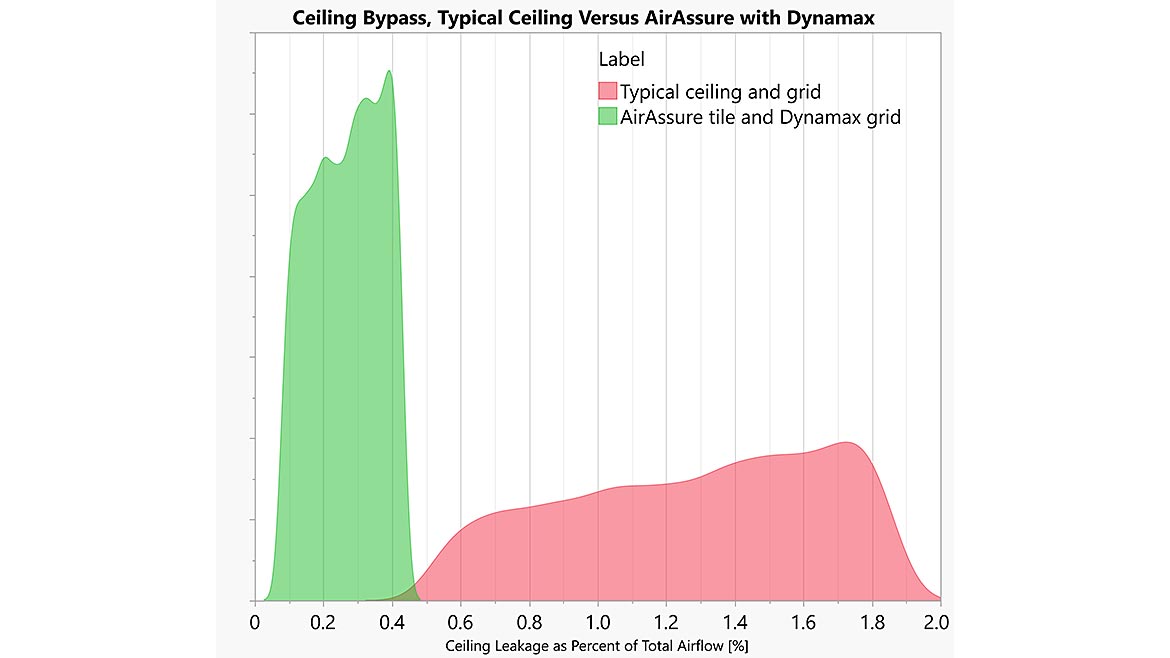
Figure 6: Typical high leakage suspended ceilings may have bypass leakage rates of 0.4 to 2.0 percent for total HVAC system flow (right distribution). Newly developed low leakage ceiling systems reduce that bypass leakage to below 0.5 percent of total HVAC system flow (left distribution).
Conclusions
Energy efficiency will continue to be a top concern for data centers in the future. Data center designers and owners must carefully evaluate all options. When thinking about containment, ceilings, suspension, and enclosures all must work together. Ceiling and grid systems form return air plenums in data centers and separate cold supply air from warm return air. Leaks across this containment plane contribute to bypass losses, increased fan energy, and increased operating cost. The use of gasketed ceiling tiles with structural grid reduces leakage rates to very low levels. This will make new and future data centers greener and more environmentally conscious.
*This is an abbreviated version of a paper written by Gordon Johnson (Subzero Engineering) and Bill Frantz (Armstrong World Industries).
Looking for a reprint of this article?
From high-res PDFs to custom plaques, order your copy today!


