All Things Gypsum
More on Area Separation Walls
However, fire resistance is not the only feature that a gypsum board area separation wall is expected to provide. Another feature expected or required of an area separation wall is its sound-attenuating properties, i.e., its ability to dampen unwanted sound from adjoining units.
Obviously, townhouse dwellers do not wish to hear the comings and goings of their neighbors and the building codes have provided for this concern in varying degrees over the years. Though the language found in today's codes may be more permissive than what once appeared in previous codes, the current codes do continue to address the concern. The term used to define a building assembly's sound attenuating properties is sound transmission class. More on what that means in a minute.
Residential codes
The 2003 International Residential Code, which defines provisions for townhouses constructed to a height of three stories or less, contains language addressing sound transmission in Appendix K. Section AK 102 therein states:"Airborne sound insulation for wall and floor-ceiling assemblies shall meet a sound transmission class rating of 45 when tested in accordance with ASTM E 90."
Since this passage appears in an appendix, it is non-mandatory and consequently its acceptance and adoption will vary from jurisdiction to jurisdiction. But jurisdictions are as likely as not to adopt the whole code; so being mindful of this provision is at least prudent, if nothing else.
The National Fire Protection Association's NFPA 5000, "Building Construction and Safety Code," offers more stringent sound control language as a requirement, found in section 49.4.2 (A), which states:
"All interior walls and floor-ceiling assemblies that separate living units, and that separate living units and spaces not a part of the living unit, shall have a sound transmission class of not less than 50 for airborne noise when tested in accordance with ASTM E 90, ‘Standard Test Method for Laboratory Measurement of Airborne Sound Transmission Loss of Building Partitions and Elements'."
NFPA 5000 has yet to enjoy widespread acceptance but its provisions may affect what is ultimately adopted in various jurisdictions weighing their options.
ASTM E 90, "Standard Test Method for Laboratory Measurement of Airborne Sound Transmission Loss of Building Partitions," specifies the procedure for measuring sound transmission loss under laboratory conditions. The STL is the difference between the sound energy (sound pressure level) measured in a source room and the sound energy measured in a receiving room when the two rooms are separated by the building system being tested. A curve plotting the STL measured at 16 different frequencies, every third octave between 125 and 4,000 Hz (cycles per second) is plotted and compared to a "reference contour," a curve that demonstrates whether the measured frequencies are within a valid range of each other to ensure that the test is accurate.
Assuming the plotted curve conforms sufficiently to the reference contour, the STL that occurs at 500 Hz is used as the indicator for STC. Or more simply stated, if the sound pressure level in the source room is measured at 100 dB at 500 Hz and the sound pressure level at the same frequency in the receiving room is measured at 40 dB, the STC of the tested assembly is 60.
Fire resistance
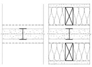
The Gypsum Association publication GA-600, "Fire Resistance Design Manual," offers several different designs for gypsum board area separation walls. Most designs indicate both a fire-resistance rating, indicating the number of hours the system has been shown through testing to withstand exposure to fire, and an STC rating, indicating the comparative level of sound the system has demonstrated that it will attenuate based on an ASTM E 90 test as described above. The systems are grouped by their hourly fire-resistance rating (two or three hours) and then ranked starting with the highest to lowest STC rating.Each system listed in the FRDM is a stand-alone system; no single system sets a general requirement that is applicable to all other systems. However, the systems ASW 1000, ASW 1001, ASW 1003, and ASW 1005 depicted in the FRDM all use a similar configuration-the main distinctions between them being the proprietary materials used, most notably the type and thickness of insulation, and the different testing facilities involved. These assemblies consist of a core constructed of two layers of 1-inch gypsum shaft-liner board supported by cold-formed steel H-studs between the panels and U-shaped cold-formed steel track at the top and bottom.
A 3/4-inch airspace between the metal framing members and any adjacent structure on either side is required for each of these systems to meet the criteria of the fire-resistance rated design. In other words, there should be no combustible material located within 3/4-inch of the steel H-studs or the U-shaped steel track. Installing 6-inch wide gypsum board battens over the H-studs allows the 3/4-inch clearance requirement to be voided, as does applying a layer of gypsum board over the entire face of the liner panel and steel framing member configuration.
The designs in the FRDM for each of the systems listed above show both the design of the system for fire resistance testing purposes and the design used for sound transmission classification testing. The graphic of the STC rated system includes flanking walls on either side of the core that are not shown in the graphic of the fire resistance-rated system. The flanking walls include the aforementioned 3/4-inch air space, 2x4 wood studs positioned directly in front of the core's steel H-studs, mineral fiber or fiberglass insulation between the wood studs and a face layer of 1/2-inch regular gypsum board. This system combined uses a total of 3 inches of gypsum board, a 3/4-inch air gap and 3 to 3 1⁄2 inches of insulation to produce a system that offers an STC rating of 55 to 64, well above the code recommended/required 45 or 50 STC rating.
Other area separation wall designs in the FRDM use a different approach to sound attenuation, typically using an insulation material somewhere within the wall's cavity-several of the designs have internal cavities-that result in STC ratings between 45 and 49. The advantage of most of these systems is that they do not require the extra materials necessary to construct flanking walls, but they don't offer the same level of protection from noisy neighbors either.
To ensure that maximum sound attenuation is realized from an area separation wall, and any other noise-reducing design, that system must be essentially airtight. If air can pass through an opening in the building system, so can sound. Since the flanking walls of the area separation wall systems first described above are likely to be used as interior surfaces in living areas, there is a high probability that there will be penetrations for electrical, cable or plumbing systems made in them. These penetrations must be sealed up tightly with an acoustical sealant to ensure that unwanted sound does not leak though the flanking wall.
The walls must also be constructed so that sound does not have the opportunity to travel on a direct path between two points. Installing a code-approved pipe so that it functions as a conduit for sound will negate the best intentions of any acoustical sealant material, no matter how well it has been installed. Placing outlets in a configuration that allows direct transmission of noise will also negate the sound attenuating characteristics of a well-constructed wall system.
Gypsum board area separation wall systems have gained wide acceptance throughout the home building industry; not only are the systems compliant with model code fire-resistance requirements, they also can conform to architectural sound attenuation mandates. To function as sound attenuating systems, they must be installed as designed and tested, and proper attention must be given to specific sound-related construction details during system application.
Looking for a reprint of this article?
From high-res PDFs to custom plaques, order your copy today!


