All Things Gypsum
Proper Use of Control Joints
The usual explanation for cracking in a gypsum board system is movement in the building's structure that was not properly accommodated; however, gypsum board systems can also expand and contract as they react to extreme changes in temperature. In every instance, some sort of control joint or stress relief device is needed to accommodate possible system movement and to inhibit potential cracking of the gypsum board membrane.
Relief of stress
In fire-resistance rated construction, stress relief is not just an aesthetic concern but a fire safety issue, as well. Cracks or interruptions of any kind in a fire-resistance rated system caused by failure to install stress relief devices could, in the event of a fire, allow flames, smoke, hot gases, or toxic fumes to migrate through a partition or floor/ceiling assembly. Control joints and other stress relief materials incorporated in fire-resistance rated construction must be constructed or installed so that they do not negatively impact the rating of the system. Control joints installed in fire-resistance rated systems must withstand the stresses created by both the anticipated movement of a building and the potential impact of a fire.
Gypsum Association publication "GA-216-2000, Application and Finishing of Gypsum Board," and ASTM International document C 840, "Standard Specification for Application and Finishing of Gypsum Board," identify requirements for the use of control joints that are applicable to all gypsum board systems, whether fire-resistance rated or not. These requirements are intended to be the minimum requirements for the design and installation of control joints. Product manufacturers may also offer minimal requirements for the installation of control joints and other stress relief products.
Where a partition, wall or ceiling traverses a construction joint in the base building structure. Such joints include expansion joints, seismic stress relief joints or building control elements.
Where a wall or partition extends in a continuous straight plane for more than 30 linear feet. A full height-floor to ceiling-doorframe may be considered a control joint in such a wall or partition.
Control joints must be installed in rated or non-rated ceilings as follows:
• On interior ceilings constructed with perimeter stress relief, control joints must be installed so that linear dimensions between control joints do not exceed 50 feet and the total area between control joints does not exceed 2,500 square feet.
• On interior ceilings constructed without perimeter stress relief, control joints must be installed so that linear dimensions between control joints are not more than 30 feet and the total area between joints is not more than 900 square feet.
• On exterior ceilings and soffits, control joints must be installed so that the distance between control joints is not more than 30 feet and the total area between control joints is not more than 900 square feet.
• A control joint or intermediate blocking must be installed in a ceiling where the ceiling framing members change direction.
They come in threes
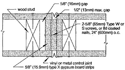
Three sample details of control joints for use in fire-resistance rated gypsum board construction systems are shown in Figures 1 through 3. Additional details are available in the previously referenced documents. Manufacturers of specialized trim pieces also publish detailed installation information. A brief discussion of each of these three configurations should provide a basic understanding of what is involved in installing a control joint in a fire-resistance rated gypsum board assembly.Figure 1 shows a detail for the installation of a control joint in a 1-hour wood-frame fire-resistance rated gypsum board wall or partition. In this design, the wood studs on either side of the joint are set 21⁄2 inches apart on floor plates and three layers of 5/8-inch fire-rated gypsum board are placed in the gap between the studs. The gypsum board is attached to the wide face of one of the studs using either 25⁄8-inch-long Type W or Type S screws or 8d-coated nails.
A nominal 5/8-inch gap is maintained between the three layers of gypsum board that are attached to the stud and the wide face of the adjacent stud. This gap provides space for the three-layer system to move laterally. The lateral movement allows the filler pieces of board to move as the partition is stressed without compromising the fire-resistance of the joint or the wall.
A vinyl or metal control joint is set into the 1/2-inch gap on each side of the wall, attached to the face of the wall and finished. Any standard control joint may be installed in the system without compromising its fire-resistance rating.
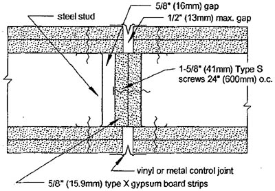
Figure 2 shows a detail for the installation of a control joint in a 2-hour fire-resistance rated wall or partition using cold-formed steel framing. Similar to the construction shown in Figure 1, in this design, two cold-formed steel studs are placed 17⁄8 inches apart with the stud webs facing each other. Two layers of 5/8-inch type-X gypsum board are attached to the web of one stud using 15⁄8-inch-long Type S screws.
As with the wood-frame system, the filler pieces of gypsum board-placed immediately behind the control joint- are installed to inhibit the passage flames, smoke, and hot gasses through the partition. To permit movement of the attached filler pieces within the stud cavity, a gap has to be maintained between the filler pieces and the web of the adjacent stud.
A vinyl or metal control joint is set into the 1/2-inch gap on each side of the wall, attached to the face of the wall and finished. Again, any standard control joint may be installed.
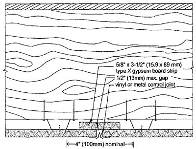
Figure 3 shows a detail for the installation of a control joint in a 1-hour fire-resistance rated floor-ceiling system with the control joint perpendicular to the framing joists. In this detail, cold-formed steel hat channel is attached perpendicular to the wood joists, spaced with 4 inches between the edges of the crowns of the channels where the joint will be placed. One layer of 5/8-inch type-X gypsum board is screw-attached to the hat channel, leaving a 1/2-inch gap between the boards for the joint. A 31⁄2-inch wide strip of 5/8-inch type-X gypsum board is placed behind the 1/2-inch gap. A vinyl or metal control joint is installed in the gap, attached to the surface of the board and finished.
All three details have permutations that allow the specifics of their construction to be transferred to a similar system. For example, the one-hour wood-frame system shown has a one-hour steel-frame counterpart similar in design to the two-hour steel-frame system illustrated. In addition, 1-hour ceiling systems that accommodate control joints installed parallel to supporting framing also have been tested.
Looking for a reprint of this article?
From high-res PDFs to custom plaques, order your copy today!


