Air, Water, Vapor Barriers: What Matters Most
Field guidance on barrier roles, testing, and install details that drive airtightness and durability.
Key Takeaways
- Air, water, and vapor barriers serve different functions and require separate performance testing.
- Material labels matter less than assembly design, detailing, and installation quality.
- Continuous air barriers and exterior insulation help reduce condensation risk and improve durability.
Water-resistive barriers and vapor barriers have long been part of wall and ceiling assemblies. Air barriers are a more recent code focus, including adoption into the Massachusetts Building Code in 2021. That shift raised a practical question for contractors: what qualifies as an air barrier in the field?
Confusion persists because air, water, vapor and thermal control layers often overlap in function. For drywall and ceiling professionals, the distinction is not academic—it directly affects airtightness, condensation risk, and assembly durability. Understanding how these materials are defined, tested and installed is critical to meeting performance requirements.
Materials
At the material level, definitions are clear and test-driven.
An air barrier material is one that restricts airflow to a maximum leakage rate of 0.02 L/(s·m²) at 75 Pa, tested in accordance with ASTM E2178. This threshold determines whether a product can be designated as an air barrier material.
A water-resistive barrier material resists liquid water intrusion. Testing typically involves spray or hydrostatic pressure exposure, with AATCC TM 127 commonly used to verify resistance to penetration.
AATCC TM 127 Hydrostatic Head Test Apparatus
Photo: Air Barrier Association of America
All three material types are designed to control the movement of air, liquid water or water vapor. However, each property must be verified independently through testing.
Material Functions
Many materials serve multiple control functions. Most WRBs also qualify as air barrier materials, though exceptions exist where water resistance does not coincide with low air leakage.
All materials have a measurable vapor permeance, placing them within Class I, II, III or higher. This means every material functions as a vapor retarder to some degree, even if that is not its intended role.
Thermal control adds another layer. Insulation affects temperature gradients, which in turn influence vapor drive and condensation risk. Some materials provide a single function; others provide two or three; a limited number can address all four control layers—air, water, vapor and heat.
This functional overlap is a common source of jobsite confusion. The key is to rely on tested performance values rather than assumptions about product category.
ASTM E96 specimen
Photo: Air Barrier Association of America
Building Assembly Design
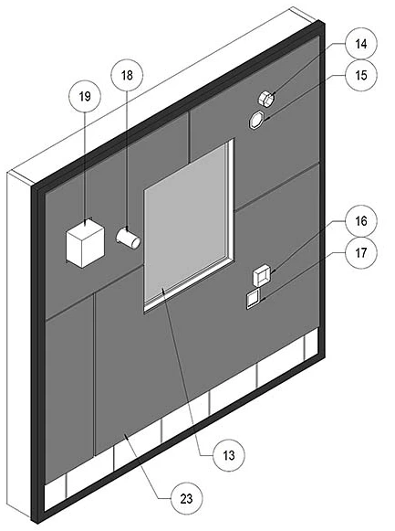
Air Barrier Assembly Specimen
Photo: Air Barrier Association of America
A material’s tested capability does not guarantee its role in an assembly. Design intent governs function.
Gypsum board meeting thickness requirements can qualify as an air barrier material, but in most wall and ceiling assemblies it is not detailed to serve as the primary air control layer. Similarly, polyethylene sheet qualifies as an air barrier material but is typically specified and installed as a vapor retarder.
Cellular plastic insulation can meet air barrier criteria at certain thicknesses and may also function as a WRB and vapor retarder. In practice, it is often used primarily for thermal control unless the assembly is specifically designed for multi-function performance.
For contractors, this distinction is critical: performance depends on how the material is detailed, not just how it is labeled.
Installation
Installation quality determines whether a material actually performs its intended function.
A WRB must be installed on the exterior side of the assembly to manage bulk water. Air barrier continuity requires sealing of joints, fasteners and penetrations, along with adequate substrate support to resist design loads.
Even dedicated air barrier systems—self-adhered or fluid-applied—fail if transitions and penetrations are not properly detailed. Discontinuities at control joints, deflection heads or ceiling interfaces are common failure points in gypsum assemblies.
Polyethylene installed as a vapor retarder in residential construction illustrates the difference. When used only for vapor control, sealing requirements are minimal. To function as an air barrier, it must be continuous, supported, overlapped and sealed at all seams, terminations and penetrations—often using acoustical sealant.
Field execution, not product selection alone, determines whether assemblies meet airtightness targets.
Guarded Hot Box Apparatus
Photo: Air Barrier Association of America
Placement of Materials
Material location within the assembly affects performance, particularly for condensation control.
Insulation placed between steel studs can result in thermal bridging and reduced effective R-value. Air leakage carrying moisture into the cavity can condense on cold exterior sheathing, leading to mold, corrosion or deterioration.
Continuous exterior insulation shifts the dew point outward, reducing condensation risk. When combined with a continuous air barrier, this approach significantly improves durability.
Assembly testing, such as guarded hot box evaluation, can measure thermal transmittance, air leakage and water resistance under controlled conditions. However, most tests are steady state, while actual weather conditions vary hourly.
Advanced modelling using climate data provides a more accurate picture of vapor movement and long-term performance, which is increasingly relevant for high-performance enclosures.
Dealing with Confusion
Misinterpretation often stems from relying on past practice rather than verified data. Contractors should start with manufacturer test results for air leakage, water resistance and vapor permeance, then review installation requirements for each intended function.
Once the assembly is defined, evaluate how air, water, vapor and heat will move through it. Confirm that each control layer is continuous and properly located.
Technical data sheets are a starting point, not a substitute for assembly-level understanding. Performance depends on how materials are integrated, detailed and installed in the field.
Looking for a reprint of this article?
From high-res PDFs to custom plaques, order your copy today!


